Test chart, test chart measurement method, and test chart measurement apparatus

a test chart and measurement method technology, applied in the field of test chart and measurement method, can solve the problems of difficult to avoid density non-uniformity, provide a high-resolution reading mechanism of this kind inside a printing apparatus, and achieve the effect of accurately measuring the position of line patterns within the test char

Inactive Publication Date: 2009-04-02
FUJIFILM CORP
View PDF7 Cites 47 Cited by
  • Summary
  • Abstract
  • Description
  • Claims
  • Application Information

AI Technical Summary

Benefits of technology

[0036]According to the present invention, since a plurality of reference line patterns having differentiated line characteristic quantities are arranged at either end portion of the line pattern block, then even supposing that a portion of the reference line patterns were to be omitted due to a recording abnormality, it is still possible to identify the line patterns on the basis of a previously ascertained distribution of the reference line patterns. There

Problems solved by technology

In an inkjet recording apparatus having a recording head comprising a plurality of ink ejection ports (nozzles), problems of image quality arise due to the occurrence of density variations (density non-uniformities) in the recorded image caused by variations in the ejection characteristics of the nozzles.
In the case of a serial (shuttle) scanning method which performs image recording by moving a recording head a plurality of times over a prescribed printing region, it is possible to avoid density non-uniformities relatively easily by means of a so-called multi-pass printing operation, but in the case of a single-pass method (a line head which performs image recording by means of a single scanning action), using a broad-width line head having a nozzle row corresponding to the width of the paper, it is difficult to a

Method used


Image

  • Test chart, test chart measurement method, and test chart measurement apparatus
  • Test chart, test chart measurement method, and test chart measurement apparatus
  • Test chart, test chart measurement method, and test chart measurement apparatus

Examples


Embodiment Construction

[0074]A preferred embodiment of the present invention is described below, with reference to figures.

[0075]Here, an example of the application to the measurement of the dot deposition positions and dot diameters of the ink dots formed by an inkjet recording apparatus is described. Firstly, the overall composition of an inkjet recording apparatus will be described.

Description of Inkjet Recording Apparatus

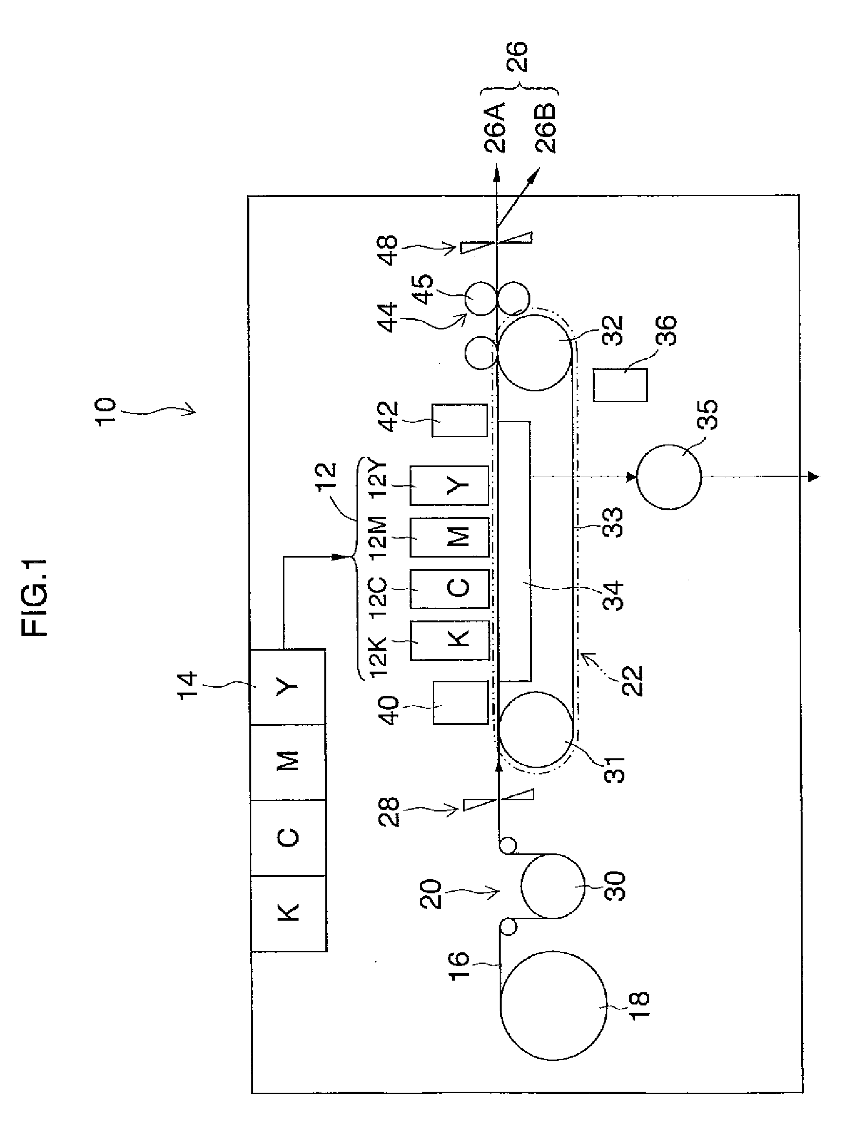
[0076]FIG. 1 is a general schematic drawing of an inkjet recording apparatus. As shown in FIG. 1, the inkjet recording apparatus 10 comprises: a print unit 12 having a plurality of inkjet recording heads (corresponding to “liquid ejection heads”, hereinafter, called “heads”) 12K, 12C, 12M and 12Y provided for ink colors of black (K), cyan (C), magenta (M), and yellow (Y), respectively; an ink storing and loading unit 14 for storing inks to be supplied to the heads 12K, 12C, 12M and 12Y; a paper supply unit 18 for supplying recording paper 16 forming a recording medium; a decurling uni...


PUM


Abstract

A test chart is recorded on a recording medium by means of a line head having a plurality of recording elements by causing the plurality of recording elements to perform recording operation while moving the recording medium and the line head relatively to each other in a relative movement direction. The test chart includes: a line pattern block which includes a plurality of line patterns respectively corresponding to the plurality of recording elements, the plurality of line patterns being arranged at a prescribed interval or above so as to be separated from each other, wherein the plurality of line patterns include reference line patterns arranged on both end regions of the line pattern block, the reference line patterns having line characteristic quantities different from the others of the plurality of line patterns.

Description

BACKGROUND OF THE INVENTION[0001]1. Field of the Invention[0002]The present invention relates to a test chart and method of measuring same, a test chart measurement apparatus and a computer-readable medium storing instructions causing a computer to measure a test chart, and in particular to a test chart and technology for measuring same suitable for measuring the dot characteristics (e.g., the depositing position, dot diameter, and the occurrence of ejection failures and other abnormalities) of each recording element in a line head installed in an inkjet recording apparatus.[0003]2. Description of the Related Art[0004]In an inkjet recording apparatus having a recording head comprising a plurality of ink ejection ports (nozzles), problems of image quality arise due to the occurrence of density variations (density non-uniformities) in the recorded image caused by variations in the ejection characteristics of the nozzles. In the case of a serial (shuttle) scanning method which performs...

Claims


Application Information

Patent Timeline
IPC IPC(8): B41J29/393
CPCB41J2/2142B41J29/38B41J2/2146B41J2202/21B41J29/393
Inventor YAMAZAKI, YOSHIROU
Owner FUJIFILM CORP
Why Eureka
Try Eureka