Vibration isolating unit, image taking unit, and image taking apparatus

a technology of vibration isolating unit and image taking unit, which is applied in the field of vibration isolating unit and image taking unit, which can solve the problems of reducing the thickness of the body and disturbing the miniaturization, and achieve the effect of reducing the amount of blurring

Inactive Publication Date: 2009-04-02
FUJI PHOTO OPTICAL CO LTD
View PDF8 Cites 7 Cited by
  • Summary
  • Abstract
  • Description
  • Claims
  • Application Information

AI Technical Summary

Benefits of technology

[0007]In view of the foregoing, it is an object of the present invention to provide a vibration isolating unit which is preferably installed in a digital camera contributing to miniaturization and reducing the thickness of the body by the use of the bending optical system, an image taking unit having the vibration isolating unit, and an image taking apparatus having the image taking unit.
[0015]In other words, the first driving section and the second driving section are disposed in parallel at a place aligned in the X-direction of the image sensor holder. This feature makes it possible to reduce the size of the image sensor of the vibration isolating unit in Y-direction (that is, the thickness direction of the digital camera), so that the vibration isolating unit can be suitably accommodated in the digital camera which contributes to miniaturization and thinness.
[0018]This feature makes it possible to use a voice coil motor, which comprises the magnet and the coil board, as a driving source for individual driving section of the vibration isolating unit of the present invention.
[0020]This feature makes it possible to become easy for neither the first coil board CL1 nor the second coil board CL2 to receive electromagnetic interference mutually.
[0021]To achieve the above-mentioned objects, the present invention provides an image taking that has a lens-barrel unit including a bending optical system wherein a subject light incident along a first optical axis extending in Y-direction toward the subject to a direction along a second optical axis extending in Z-direction perpendicular to Y-direction so as to make image-formation, and that has a vibration isolating unit including an image sensor for creating an image signal representing the subject through image-formation of the subject light by the bending optical system and moves the image sensor so that the vibration isolating unit suppresses blurring on the image signal, wherein the vibration isolating unit includes:
[0027]To achieve the above-mentioned objects, the present invention provides an image taking apparatus having the image taking unit as defined in claim 4, wherein the image taking apparatus generates an image signal in which blurring is reduced by operation of the vibration isolating unit constituting the image taking unit.

Problems solved by technology

Even if it is intended to contributing to miniaturization and reducing the thickness of the body by using the above-mentioned bending optical system, some structure of a vibration isolating mechanism may disturb miniaturization and reducing the thickness of the body due to the vibration isolating mechanism.

Method used


Image

  • Vibration isolating unit, image taking unit, and image taking apparatus
  • Vibration isolating unit, image taking unit, and image taking apparatus
  • Vibration isolating unit, image taking unit, and image taking apparatus

Examples


Embodiment Construction

[0053]Embodiments of the present invention will be described with reference to the accompanying drawings.

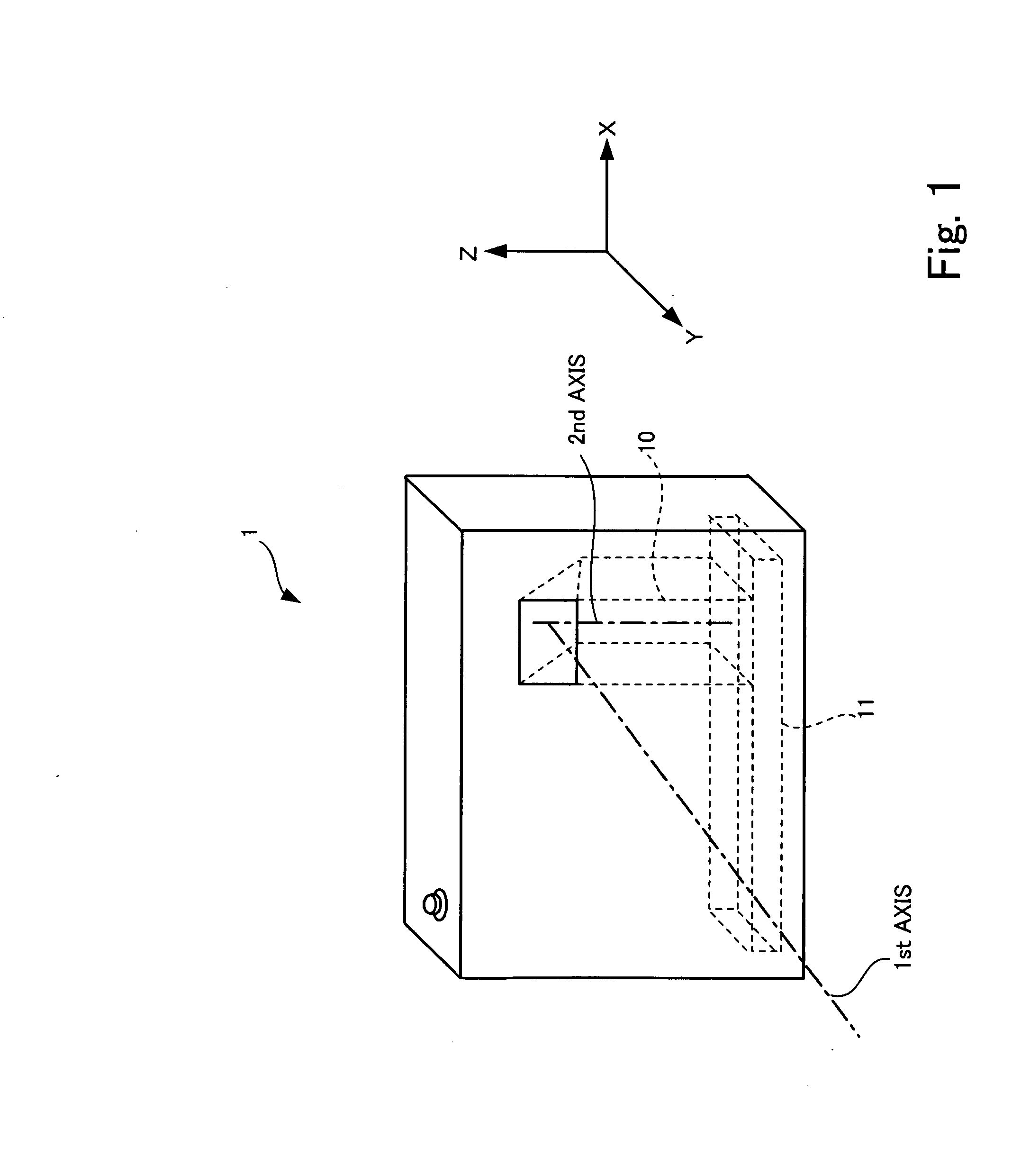
[0054]FIG. 1 is a perspective view of a digital camera 1 to which an embodiment of the present invention is applied.

[0055]FIG. 1 shows a perspective view of the digital camera 1 which adopts a lens-barrel unit 10 incorporating a bending optical system to contribute to miniaturization and reducing the thickness of the body of the digital camera 1.

[0056]Since FIG. 1 shows a three-dimensional perspective view, FIG. 1 shows the axes of coordinates that represent X axis, Y axis, and Z axis to make the direction of X, the direction of Y, and the direction of Z used in the following explanations comprehensible. To indicate the direction in figures following FIG. 2 too, all the axes of coordinates are shown in the figures.

[0057]In the preferred embodiments of FIG. 1 to FIG. 24 which will be described hereinafter, there will be shown examples in which the direction of X represented by the...


PUM


Abstract

Y-driving section is disposed in X-direction of an image sensor holder, and a slider is arranged for the image sensor holder to come in succession to Z-direction and extend to X-direction, so that X-driving section is disposed at the end of the slider. Regarding Y-direction, Y-driving section directly drives the image sensor holder. Regarding X-direction, X-driving section drives the slider and indirectly drives the image sensor holder in X-direction.

Description

BACKGROUND OF THE INVENTION[0001]1. Field of the Invention[0002]The present invention relates to a vibration isolating unit for correcting blurring on an image, an image taking unit having the vibration isolating unit, and an image taking apparatus having the image taking unit.[0003]2. Description of the Related Art[0004]Recently, in an image taking apparatus, there is one which incorporates therein a vibration isolating mechanism to suppress a disturbance of a photographic image caused by camera shake of a user and the like. According to the vibration isolating mechanism, optical components such as a correction lens and an image sensor are movably disposed in a plane perpendicular to an optical axis. A correction of the camera shake is carried out when the correction lens or the image sensor are driven in accordance with the camera shake. Japanese Patent document 1 (Japanese Patent Application Laid Open Gazette TokuKai Hei. 3-186825), Japanese Patent document 2 (Japanese Patent App...

Claims


Application Information

Patent Timeline
Patent Type & Authority Applications(United States)
IPC IPC(8): H04N5/228H04N5/225
CPCG03B5/00
Inventor SUZUKI, YUSUKEOMIYA, AKIONOGUCHI, YUKIOKAWANABE, YUICHITAKATORI, NAOKOISHIKAWA, YOSHIHIROGODA, YOKICHI
Owner FUJI PHOTO OPTICAL CO LTD
Why Eureka
Try Eureka