Diffraction-type optical modulator and display apparatus including the same

Inactive Publication Date: 2009-04-02
SAMSUNG ELECTRO MECHANICS CO LTD
View PDF1 Cites 35 Cited by
  • Summary
  • Abstract
  • Description
  • Claims
  • Application Information

AI Technical Summary

Benefits of technology

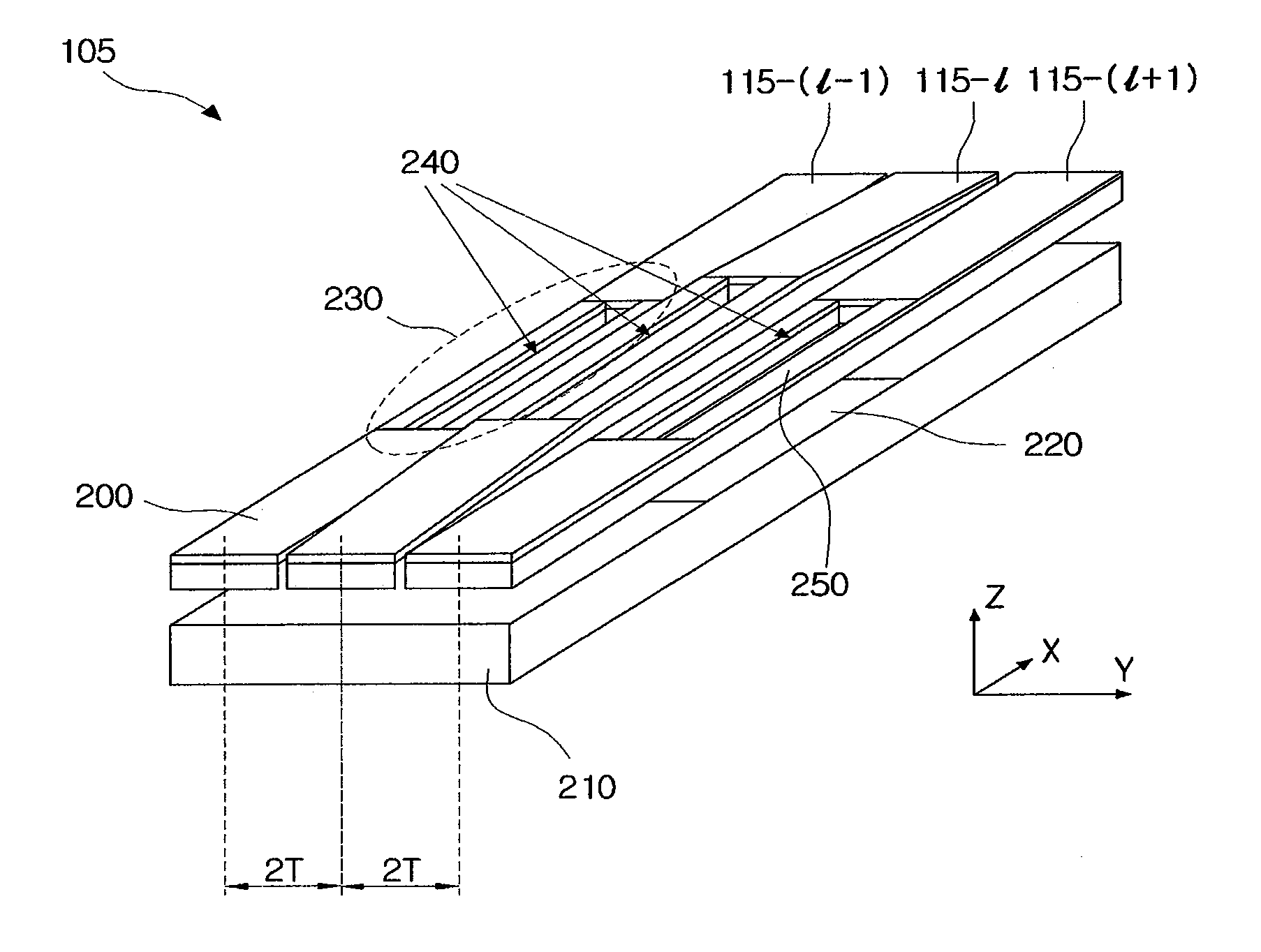
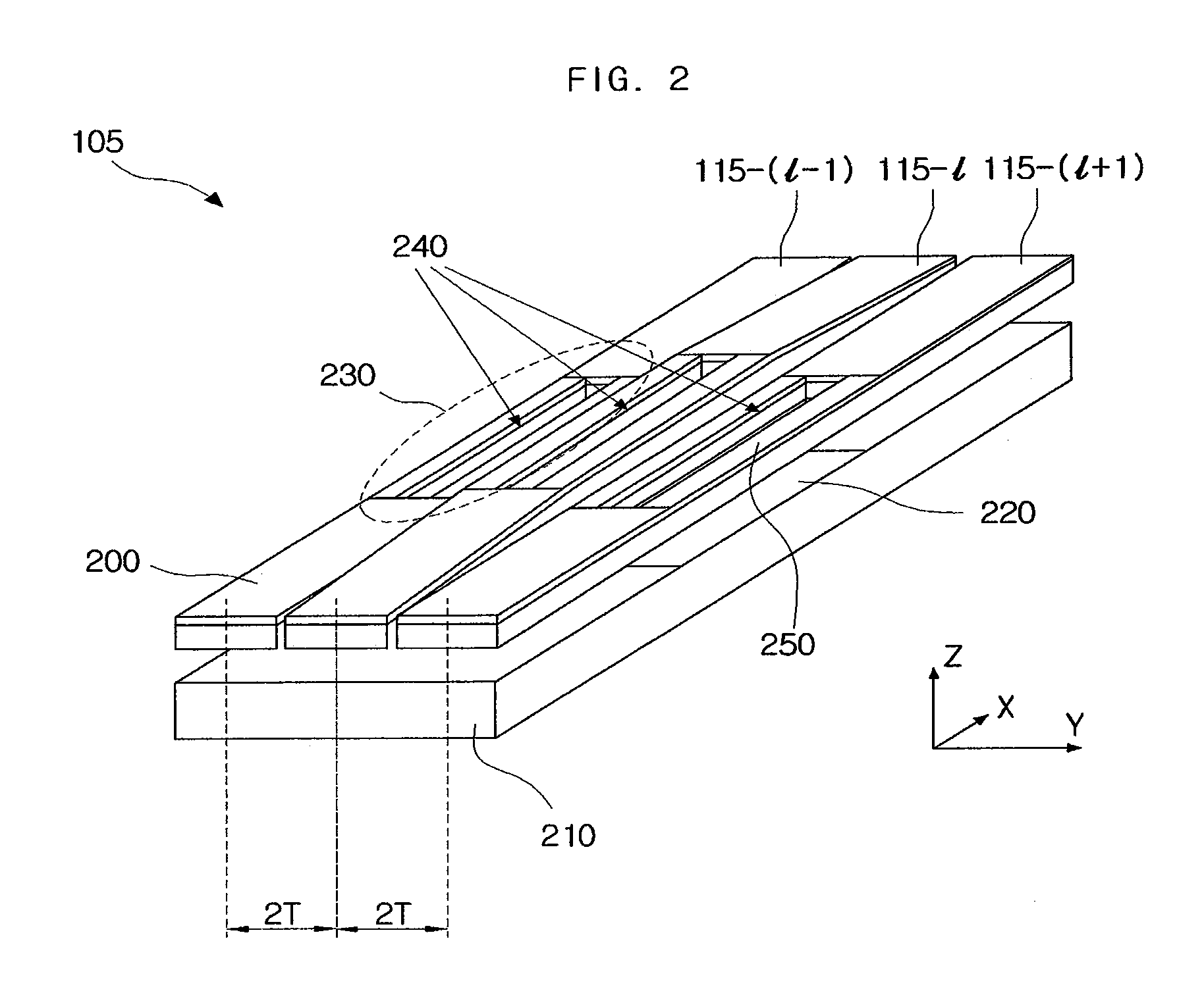
[0010]The present invention provides a diffraction-type optical modulator for maximizing a contrast ratio by using the relation between the width of the hole and the

Problems solved by technology

There is, however, a problem that a contrast ratio (CR), i.e., a ratio of the darkest luminance representable by a pixel to the brightest

Method used


Image

  • Diffraction-type optical modulator and display apparatus including the same
  • Diffraction-type optical modulator and display apparatus including the same
  • Diffraction-type optical modulator and display apparatus including the same

Examples


Embodiment Construction

[0027]Since there can be a variety of permutations and embodiments of the present invention, certain embodiments will be illustrated and described with reference to the accompanying drawings. This, however, is by no means to restrict the present invention to certain embodiments, and shall be construed as including all permutations, equivalents and substitutes covered by the spirit and scope of the present invention. In the following description of the present invention, the detailed description of known technologies incorporated herein will be omitted when it may make the subject matter unclear.

[0028]Terms such as “first” and “second” can be used in describing various elements, but the above elements shall not be restricted to the above terms. The above terms are used only to distinguish one element from the other.

[0029]The terms used in the description are intended to describe certain embodiments only, and shall by no means restrict the present invention. Unless clearly used otherw...


PUM


Abstract

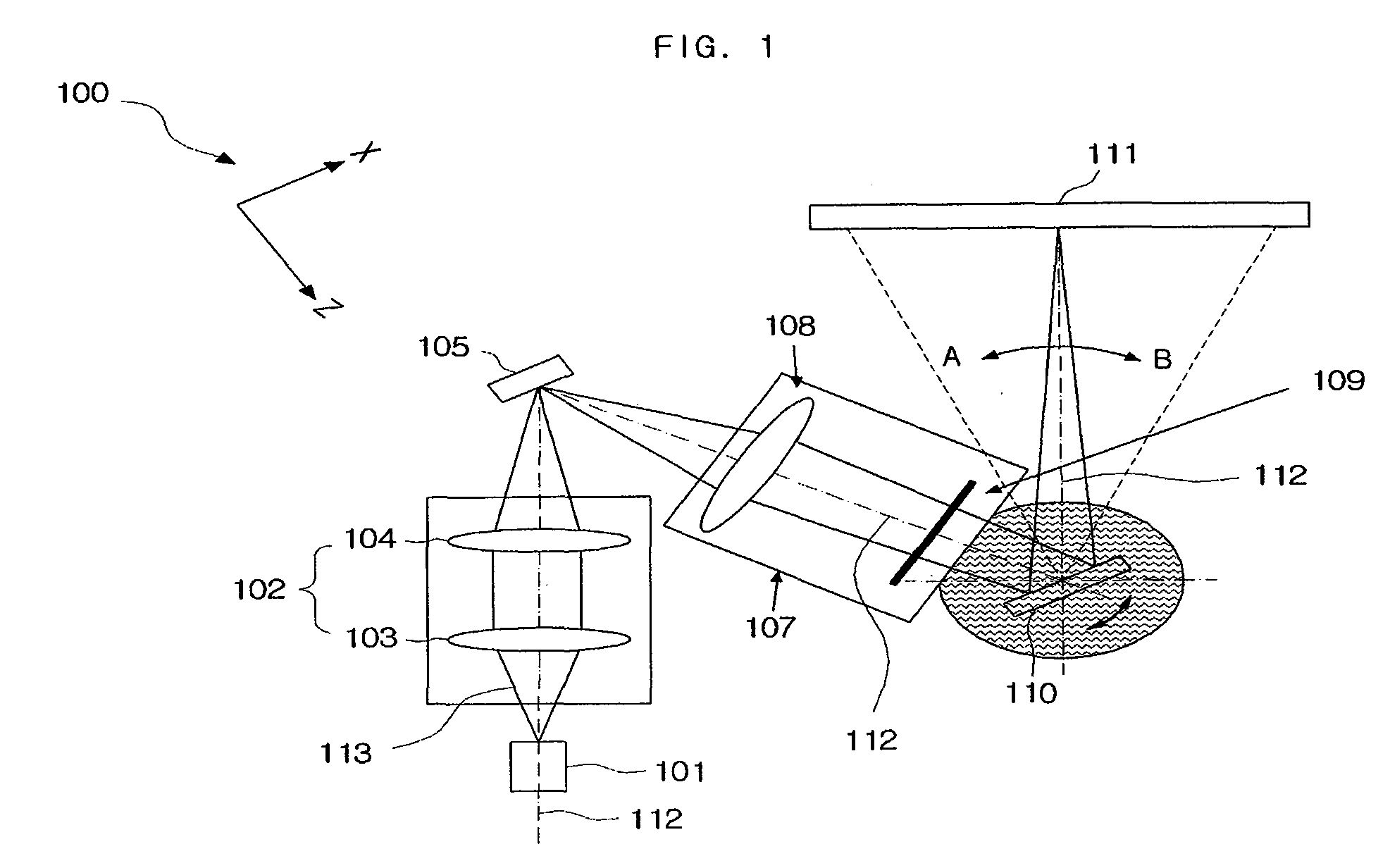
Disclosed are a diffraction-type optical modulator and a display apparatus including the same. The diffraction-type optical modulator includes: a board; a lower mirror formed on the board; an upper mirror located apart from the lower mirror by a predetermined gap, having a hole, separated into at least two ridges by the hole, and movable up and down; and, an actuator moving the upper mirror in accordance with a driving signal and changing the separation distance, whereas a part of incident light beam reflects from the upper mirror, the rest of the incident light beam passes through the hole and reflects from the lower mirror, and then passes through the hole. A contrast ratio can be maximized by using the relation between the width of the hole and the ridge of an upper mirror, the ridge being measured in parallel with the direction of distribution of diffraction gratings.

Description

CROSS-REFERENCE TO RELATED APPLICATION[0001]This application claims the benefit of Korean Patent Application No. 10-2007-0088096, filed with the Korean Intellectual Property Office on Aug. 31, 2007, the disclosure of which is incorporated herein by reference in its entirety.BACKGROUND OF THE INVENTION[0002]1. Technical Field[0003]The present invention relates to a display apparatus using an optical modulator, more particularly to a display apparatus having an improved contrast ratio through adjustment of the size of the hole of the optical modulator.[0004]2. Description of the Related Art[0005]Generally, an optical signal processing has advantages of a high speed, parallel processing ability and high-capacity information processing in contrast to conventional digital information processing incapable of processing a large amount of data in real time. In addition, research has been devoted to application of the optical signal processing to a design and manufacture of a binary phase fi...

Claims


Application Information

Patent Timeline
IPC IPC(8): G02B26/02G02F1/21
CPCG02B26/0808G02B5/1828G02B26/02G02B26/0833G02B27/4205
Inventor YURLOV, VICTORYANG, HAENG-SEOKYUN, SANG-KYEONGLAPCHUK, ANATOLIY
Owner SAMSUNG ELECTRO MECHANICS CO LTD
Why Eureka
Try Eureka