Sound source direction detecting apparatus, sound source direction detecting method, and sound source direction detecting camera

a technology of sound source direction and detecting method, applied in the direction of two-way working system, undesired wave elimination system, instruments, etc., can solve the problem of inaccuracy in detecting the location of speaking people, and achieve the effect of detecting the direction

Inactive Publication Date: 2009-04-02
SONY CORP
View PDF0 Cites 48 Cited by
  • Summary
  • Abstract
  • Description
  • Claims
  • Application Information

AI Technical Summary

Benefits of technology

[0025]Furthermore, by using consecutive audio frames, it is possible to detect the direction of the speaking person more reliably than before.
[0026]According to the embodiments of the present invention outlined above, the direction of the sound source (speaking person) is reliably detected, so that the camera in operation may be oriented in the detected directi

Problems solved by technology

When implemented, the techniques proposed so far could lead to

Method used


Image

  • Sound source direction detecting apparatus, sound source direction detecting method, and sound source direction detecting camera
  • Sound source direction detecting apparatus, sound source direction detecting method, and sound source direction detecting camera
  • Sound source direction detecting apparatus, sound source direction detecting method, and sound source direction detecting camera

Examples


first embodiment

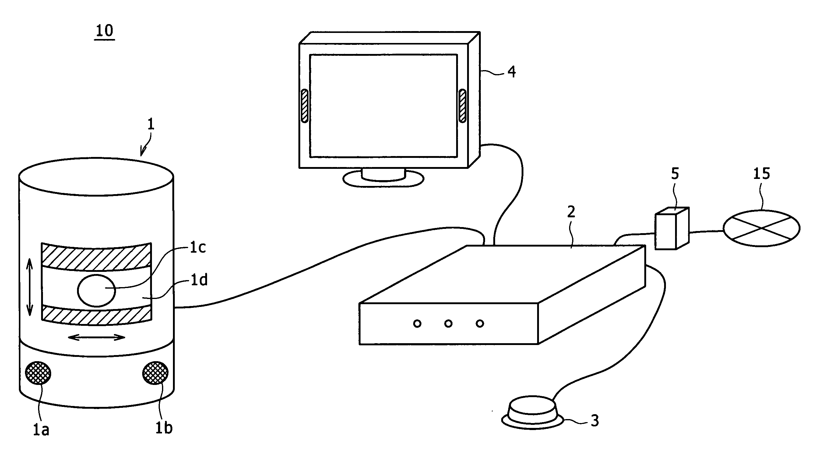
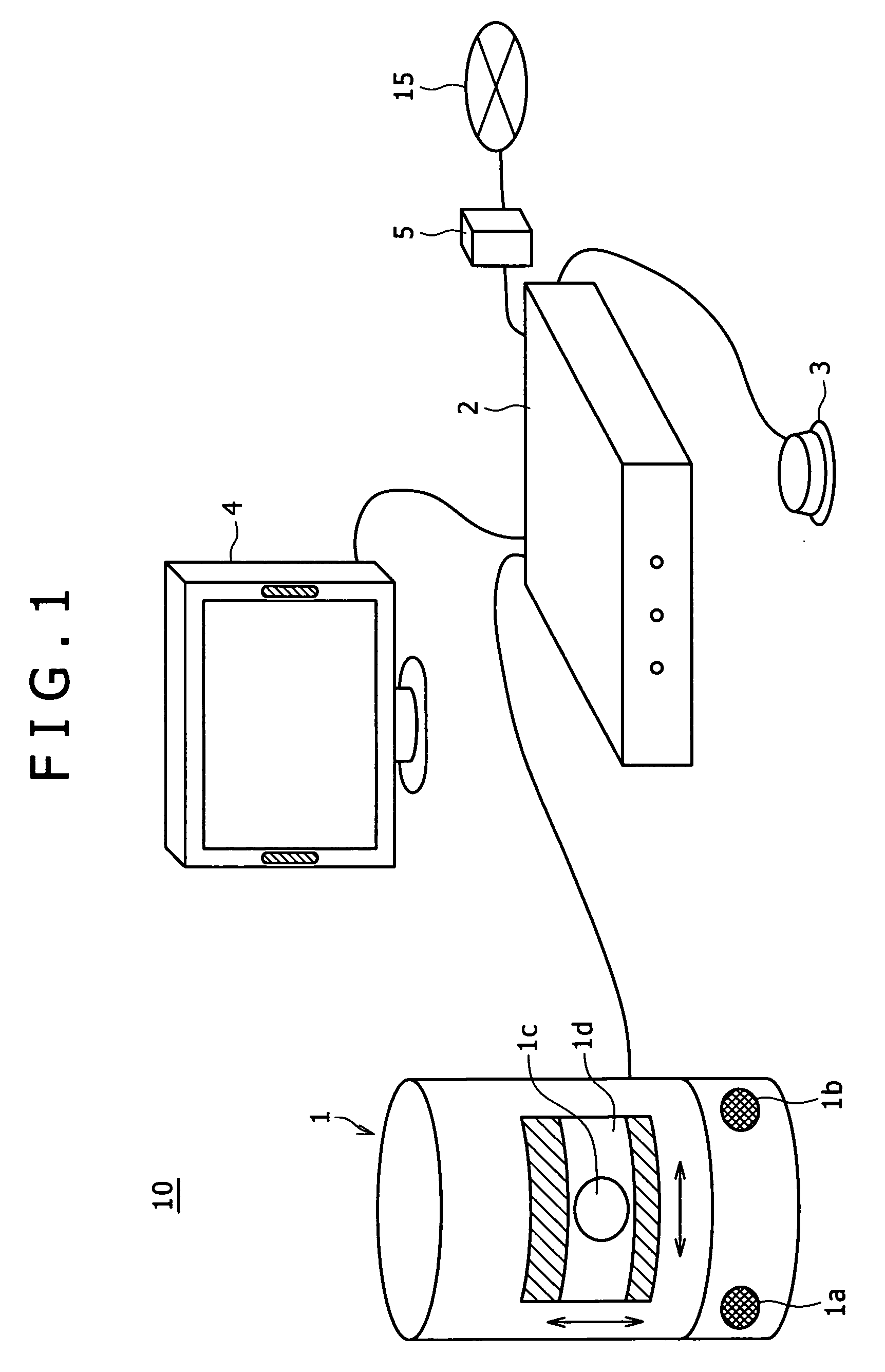
[0042]The first preferred embodiment of the present invention is described below in reference to FIGS. 1 through FIG. 6B. The first embodiment is practiced illustratively as a video conferencing system 10 capable of sending and receiving images and sounds in real time between remote locations.

[0043]FIG. 1 is an external view showing how the video conferencing system 10 of the first embodiment is typically configured. A camera 1 for imaging the speaking person contains, in the bottom portion of its enclosure, a first microphone 1a and a second microphone 1b for collecting sounds in order to detect their source. The first and the second microphones 1a and 1b are a predetermined distance apart (e.g., about 10 centimeters). The first and the second microphones 1a and 1b convert the collected sounds into an audio frame that is sent to a control device 2. The sounds collected by the first and the second microphones 1a and 1b are not used to record the speaking person's remarks but utilize...

second embodiment

[0074]Described below in reference to FIG. 9 is a typical process performed by the sound source direction detecting apparatus 40 of the second embodiment for estimating the direction of a sound source. The sound source direction detecting apparatus 40 obtains additional power levels for each of the chronologically continuous audio frames (e.g., the first and the second frames in the ensuing description) and adds up the power levels thus acquired. The process makes it possible to leave unchanged the effects of the sound source direction detected from the first frame, before proceeding to detect the sound source direction from the second frame with the remaining effects taken into account.

[0075]In step S1 of FIG. 9, the first and the second microphones 1a and 1b collect sounds, form the collected sounds into an audio frame, and send the audio frame to the control device 2. The audio frame (i.e., first frame) received by the control device 2 is converted to a digital signal that is for...


PUM


Abstract

Disclosed herein is a sound source direction detecting apparatus including: a plurality of microphones configured to collect sounds from a sound source in order to form an audio frame; a frequency decomposition section configured to decompose the audio frame into frequency components; an error range determination section configured to determine the effects of noises collected together with the sounds as an error range relative to phases; a power level dispersion section configured to disperse power levels of the sounds for each of the frequency components decomposed by the frequency decomposition section, on the basis of the error range determined by the error range determination section; a power level addition section configured to add the power levels dispersed by the power level dispersion section; and a sound source direction detection section configured to detect the direction of the sound source based on the phase at which is located the highest of the power levels added by the power level addition section.

Description

CROSS REFERENCES TO RELATED APPLICATIONS[0001]The present invention contains subject matter related to Japanese Patent Application JP 2007-252734 filed in the Japan Patent Office on Sep. 27, 2007, the entire contents of which being incorporated herein by reference.BACKGROUND OF THE INVENTION[0002]1. Field of the Invention[0003]The present invention relates to a sound source direction detecting apparatus, a sound source direction detecting method, and a sound source direction detecting camera for detecting the direction of a speaking person by analyzing the sound vocalized by that person illustratively during a conference.[0004]2. Description of the Related Art[0005]There exist video conferencing systems for linking speaking persons illustratively at remote locations during what is known as a video conference. With this type of system in operation, the remarks and gestures of the people participating in the video conference are exchanged in real time between the linked remote locatio...

Claims


Application Information

Patent Timeline
IPC IPC(8): H04R3/00H04N7/14G10L15/28G10L21/0272G10L21/028
CPCG01S3/801G01S3/86G01S3/8083
Inventor KAWAGUCHI, TAKAYOSHIKODAMA, YASUHIROSAKURABA, YOHEI
Owner SONY CORP
Why Eureka
Try Eureka