Band Saw Machine

Inactive Publication Date: 2009-04-09
KOKUHO
View PDF13 Cites 2 Cited by
  • Summary
  • Abstract
  • Description
  • Claims
  • Application Information

AI Technical Summary

Benefits of technology

[0013]For facilitating an adjustment of the machine position to a workpiece, another preferred embodiment of the invention is further provided with a retractable caster.
[0014]In a band saw machine of the present invention, a portion of a saw blade which runs into a cutting section fixed between two wheels is approximated to a basic plane with being controlled in near-parallel with the basic plane by a stabilizing member, and is pressed by a depressing mechanism with almost no gap between the saw blade and the basic plane. For example, when using for removing a protrusion on a floor face of a bottom in a ship on building, a band saw machine cuts the protrusion off with bringing a basic plane of a body frame in close contact with the floor face, namely a cutting plane, that is to say, cuts the protrusion off with placing the body frame on the floor face to be able to remove the protrusion to its root perfectly. Accordingly, an extra effort to smoo

Problems solved by technology

However, for example, in a ship on building, a protrusion on a floor face of a bottom cannot be cut to its root with the conventional band saw machine because the looped saw blade cannot be brought close to the floor face.
As a result,

Method used


Image

  • Band Saw Machine
  • Band Saw Machine
  • Band Saw Machine

Examples


embodiment

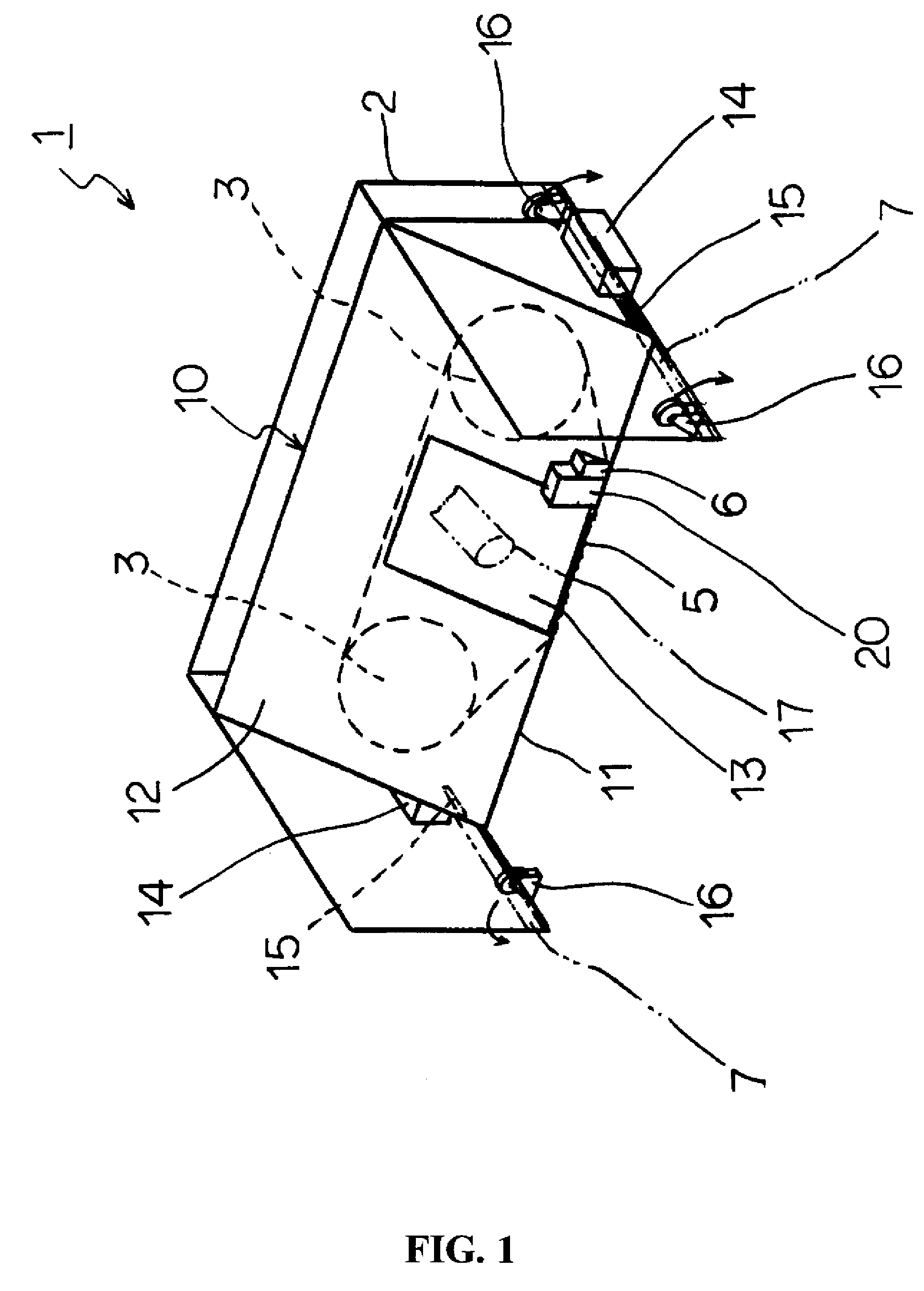
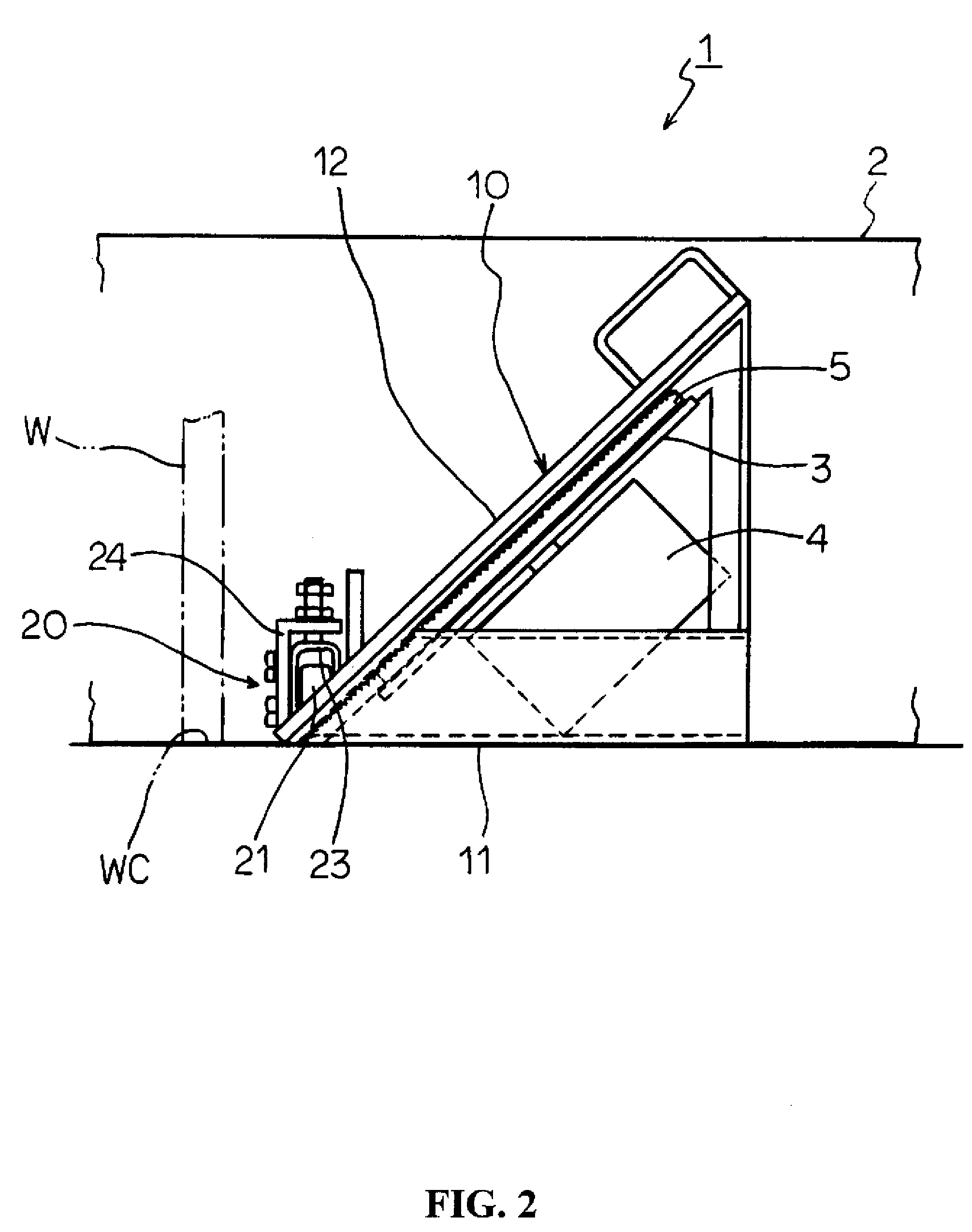
[0023]FIGS. 1 to 4 show one embodiment of a band saw machine of the invention.

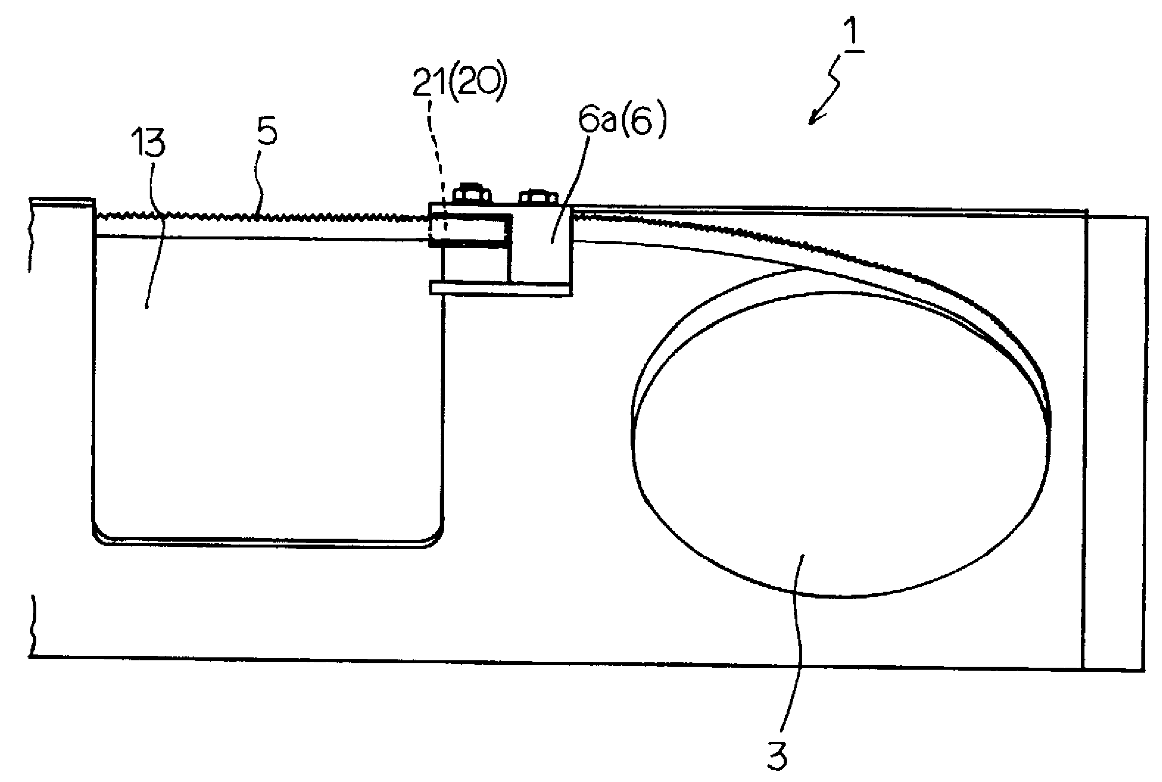
[0024]Referring to FIGS. 1 and 2, a band saw machine 1 is provided with a base frame 2 build up with plates in channel shape, a body frame 10 housed in the base frame 2, two wheels 3, 3 provided on the body frame 10 and rotating on an inclined plane 12 inclined 45 degrees to a basic plane 11 which is flush with a cutting plane WC, a motor 4, shown only in FIG. 2, supplying driving force to a first wheel 3, a saw blade 5 formed in loop and strained between the two wheels 3, 3, a stabilizing member 6 aligned near the cutting section 13 which is fixed between the wheels 3, 3 and on an edge intersected the inclined plane 12 with the basic plane 11, and a depressing mechanism 20 fixed up adjacent to the cutting section 13 side of the stabilizing member 6.

[0025]Referring to FIG. 3, the stabilizing member 6 is composed of two block 6a, 6b which are placed opposite at a predefined interval, that is a interval a li...


PUM


Abstract

A band saw machine is provided with a body frame, two wheels provided on the body frame and rotating by driving force on an inclined plane which is inclined to a basic plane which is flush with a cutting plane, a saw blade formed in loop and strained between the two wheels, a stabilizing member bringing a portion of the saw blade which runs around a cutting section which is fixed between the wheels and on an edge intersected the inclined plane with the basic plane close to the basic plane in near-parallel, and a depressing mechanism fixed up adjacent to the cutting section side of the stabilizing member to clear the gap between the saw blade and the basic plane.
The band saw machine, for example in a ship on building, can finely cut a protrusion on a floor of a bottom to its root to remove it. Thus, an extra effort to smooth a floor can be saved.

Description

FIELD OF THE INVENTION[0001]The present invention relates to a band saw machine to be used for cutting metals.DESCRIPTION OF THE RELATED ART[0002]In one example of related arts, there is a band saw machines provided with a pair of wheels which are fixed up in parallel, and a looped saw blade which runs tight between the wheels. For example, in cutting a steel product by the band saw machine, the steel product is set on a cutting section which is provided between the wheels, and is slid toward the cutting section to be cut. Otherwise, the machine is approximated to a fixed steel product to cut the product on the cutting section.[0003]The above conventional band saw machine can cut a steel product to a desired size. However, for example, in a ship on building, a protrusion on a floor face of a bottom cannot be cut to its root with the conventional band saw machine because the looped saw blade cannot be brought close to the floor face. As a result, for shaping the floor face smooth, an...

Claims


Application Information

Patent Timeline
IPC IPC(8): B27B13/00
CPCB23D53/001B23D53/04B23D53/003Y10T83/7251
Inventor KONDO, AKIHIRO
Owner KOKUHO
Why Eureka
Try Eureka