Harvesting corn cobs

a corn cob and corn technology, applied in the field of corn cobs harvesting, can solve the problems of crude current methods no commercially available equipment for collecting corn cobs, and insufficient cleaning methods to properly collect all

Inactive Publication Date: 2009-04-16
REDEKOP ENTERPRISES
View PDF22 Cites 48 Cited by
  • Summary
  • Abstract
  • Description
  • Claims
  • Application Information

AI Technical Summary

Benefits of technology

[0041]wherein the hitch coupling includes a quick detachable hitch which allows side to side and front to rear movement of a hitch coupling relative to the cart.

Problems solved by technology

There is currently no commercially available equipment to collect corn cobs and a very small number of people that have built equipment to collect cobs themselves.
Current methods to collect cobs are very crude.
Cleaning methods are not sophisticated enough to properly collect all cobs so there is a large amount of wasted cobs;
One solution includes a collection tank mounted above a combine's grain tank—making the additional load too high and too heavy for current combines; this will be very difficult to be made commercially available with the diverse number of combine designs manufactured over the last 20 years.

Method used


Image

  • Harvesting corn cobs
  • Harvesting corn cobs
  • Harvesting corn cobs

Examples


first embodiment

[0158]The following description of further embodiments of the invention discloses elements and features which may also be used in the first embodiment described above.

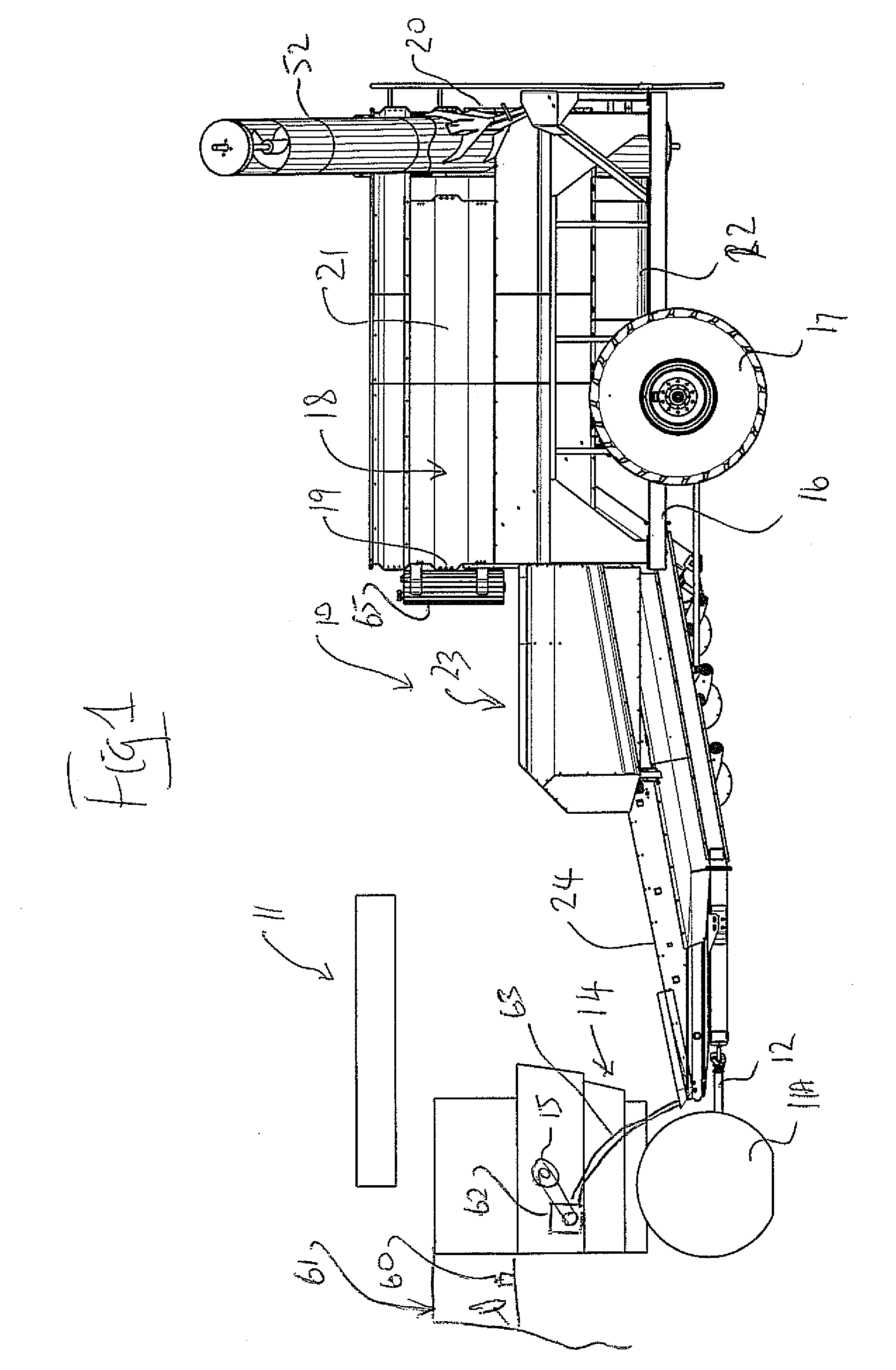
[0159]Referring to FIGS. 14 and 15, a corn cob harvesting machine 110 is pulled behind the rear end of a typical combine 111. The combine 111 is equipped with a specialized hitch 112 to quickly disconnect the cob harvesting machine, as it is a common practice to switch between harvesting corn and soybean on a daily basis dependant on the weather. The cob harvester is powered hydraulically by a drive system 113 taking power from combine's chopper drive.

[0160]The corn cob harvester includes an inlet conveyor 120 that has a feed hopper 121 placed under the combine's residue outlet 114. It is preferable that the residue from the sieves 115 as well as the walkers or rotors 116 (depending on combine type) be combined in the inlet conveyor's hopper to capture all possible cobs.

[0161]The inlet conveyor 120 elevates the residue...

third embodiment

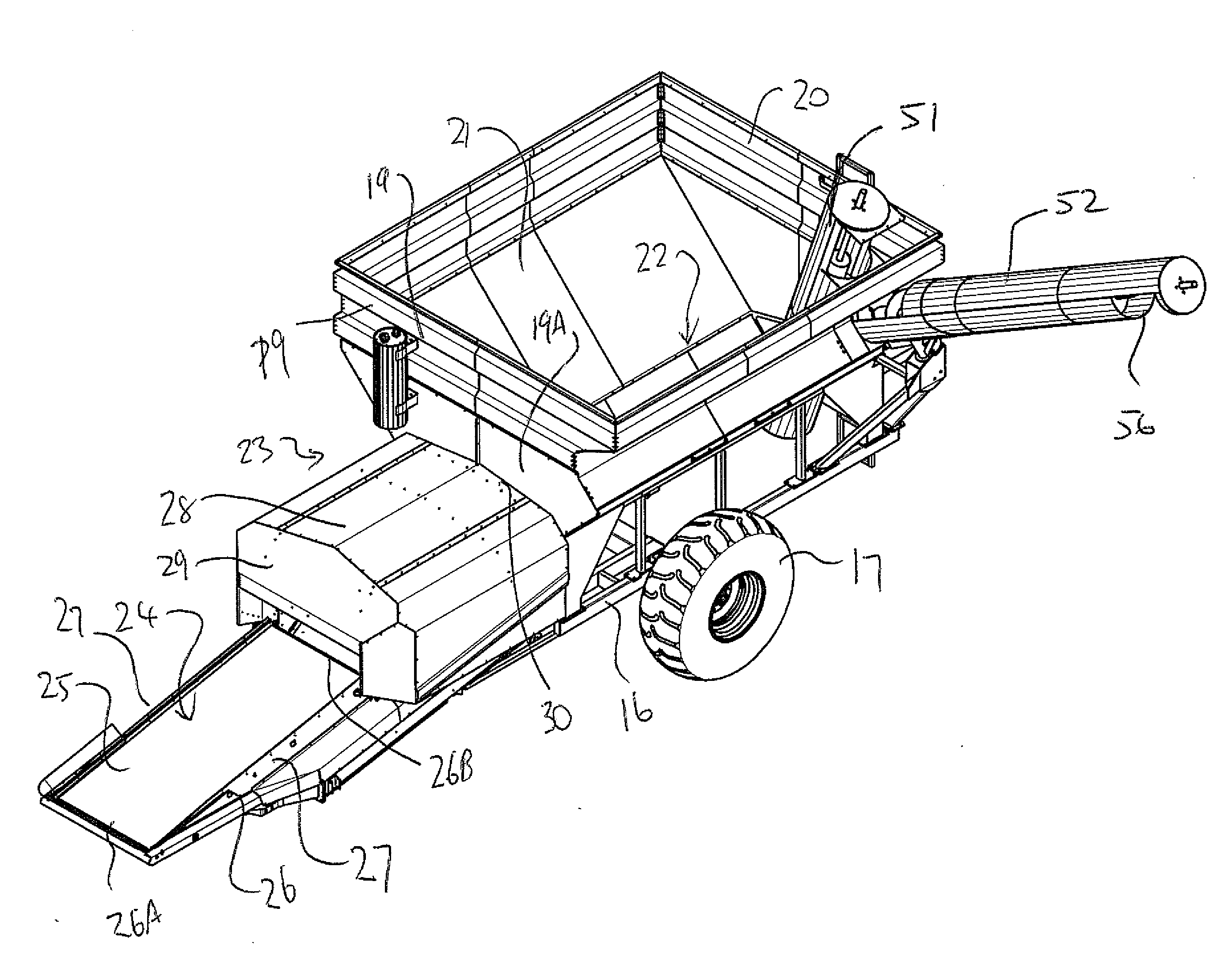
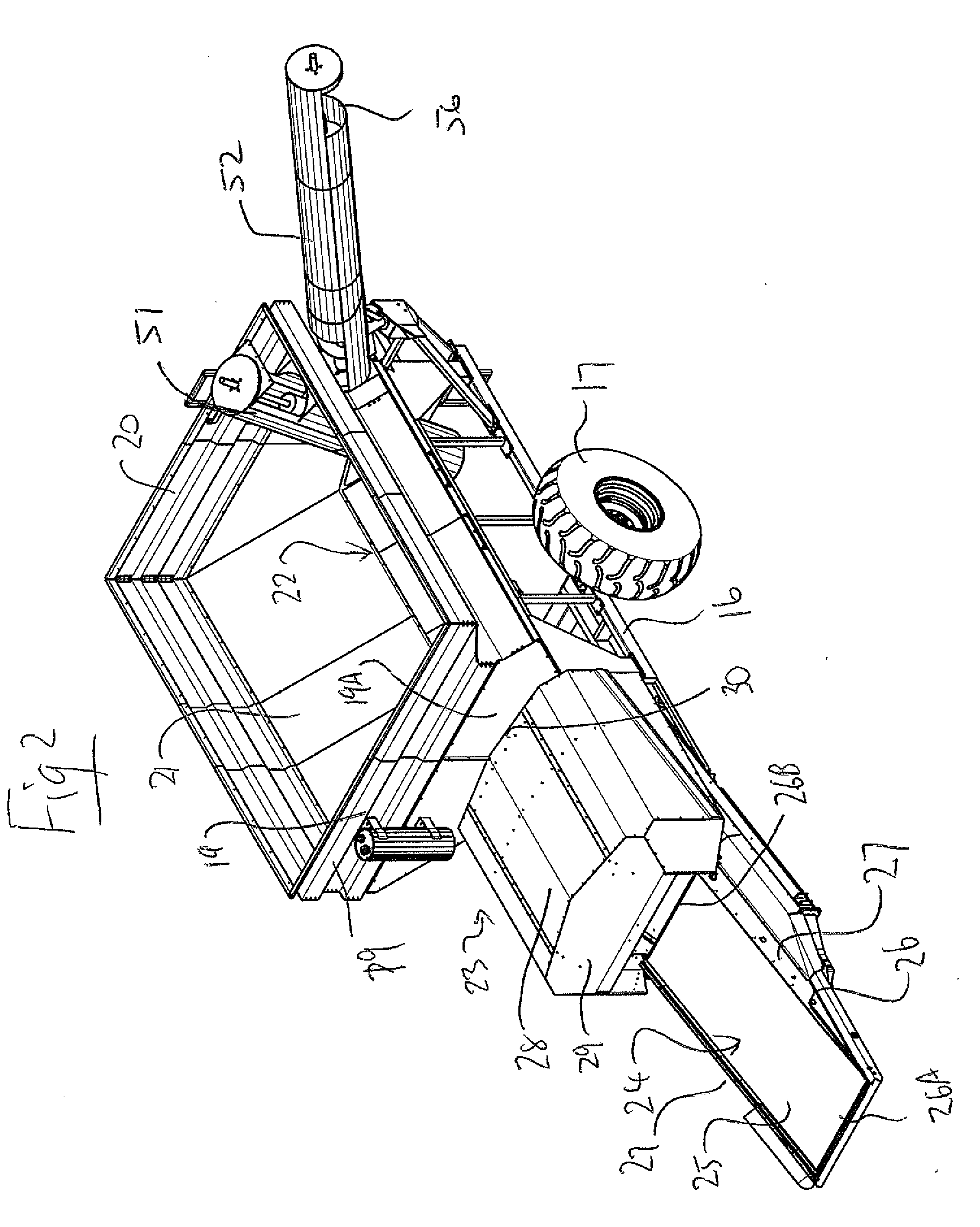
[0171]Referring now to the third embodiment shown in FIG. 21, a corncob harvesting machine 210 of the same general type as that disclosed above is pulled behind the rear end of the combine 211. The combine is equipped with a specialized hitch 212 of the arrangement previously described to quickly disconnect the cob harvesting machine. The cob harvester is powered hydraulically by a drive system (not shown) taking a drive outlet from the combine's chopper drive, again as previously described.

[0172]The corn cob harvester includes the inlet conveyor 220 that has its feed hopper 221 placed under the combine's residue outlet 214. It is preferable that the residue from the sieves as well as the walkers or rotors (depending on combine type) be collected in the inlet conveyor's hopper in order to capture all possible cobs.

[0173]The inlet conveyor elevates the residue and drops the stover into a cob separating region 280. The cob separating mechanism includes a fan 281 for generating air jet...

second embodiment

[0186]The cob separating mechanisms for the second and third stages is similar to that of the second embodiment except that each includes only a single air plenum. Thus these separating devices include the fan 381 for generating air flow and pressure, ducts 334 for transporting pressurized air to transverse air plenums 335 and 336 and holes in the plenums for creating air jets 337 to blast through the stover. Each plenum's air jet velocity can be adjusted independently with control valves 141 and the jet's trajectory can be altered with rotational adjustment of the plenum about its transverse axis. The cobs and residue fall from the upper end of the first conveyor 320 though the open space to the inlet 310 at the bottom end of the second conveyor 310 and pass through a hard air blast from air plenum 335. The air blast accelerates and lifts the lighter residue separating it from the heavier cobs. The lighter residue is directed into fins 138 mounted to the bottom side of the second s...


PUM


Abstract

A cart is towed behind a combine harvester for collecting corn cobs and includes a conveyer belt feeding into a system for separating cobs from residue to be discharged and a tank for receiving and transporting the cobs. An unload auger is provided from the tank to one side of the cart while the cart moves forward. Power for driving the cart is obtained from a chopper drive of the combine harvester. The separating arrangement includes a series of sequential blower fans for blowing air through the discharged material as it is discharged from a conveyor and into a spreading guide disperses the residue. The cobs are conveyed using a series of augers where the auger to flight distance is at least 2 inches and particularly a pair of augers feed the cobs through a front wall of the tank so as to push cobs upwardly into the tank.

Description

[0001]This application claims the benefit under 35 U.S.C. 119 of Provisional Applications Nos. 60 / 979,988 filed Oct. 15, 2007 and 60 / 986,438 filed Nov. 8, 2007 and 60 / 981,134 filed Oct. 19, 2007 and 61 / 087,409 filed Aug. 8, 2008, the disclosures of which are incorporated herein by reference.[0002]This invention relates to agricultural harvesting machines and including a device to separate the corn cobs from the residue discharged from a combine when harvesting corn. The arrangement described and claimed herein can be towed behind a combine harvester to directly receive the material from the combine harvester or may be towed separately after the combining action is complete and includes a pick-up at the front of the inlet conveyor in order to pick up the material from the groundBACKGROUND OF THE INVENTION[0003]World ethanol production is expected to experience double-digit growth in the next years. Much of the growth is expected to occur in the United States where, with the current p...

Claims


Application Information

Patent Timeline
Patent Type & Authority Applications(United States)
IPC IPC(8): B07B4/00B07C5/00B60P1/00
CPCA01D90/02A01D90/10B07B4/02B07B1/12A01D90/12
Inventor REDEKOP, LEOMAYERLE, DEANWILLEMS, SALTON
Owner REDEKOP ENTERPRISES
Why Eureka
Try Eureka