
Boundary microphone

Active Publication Date: 2009-04-16
AUDIO-TECHNICA
View PDF6 Cites 10 Cited by
  • Summary
  • Abstract
  • Description
  • Claims
  • Application Information

AI Technical Summary

Benefits of technology

[0015]Since the internal components are disposed in the space enclosed by the base and the cover and furthermore the internal components are enclosed by the base, the cover, the first metallic part, and the second metallic part whose peripheral portions are alternately overlapped, the electromagnetic waves which are to enter toward the internal components from the outside can be blocked more effectively. For example, even if a mobile phone using a high frequency electromagnetic wave, such as 2 GHz, is used close

Problems solved by technology

The reason is, if the connecting portions are not joined together appropriately but the base and the cover are in point contact with each other and there is a gap therebetween, high frequency noise will enter from this gap.
However, the peripheral portion, which is electrically and mechanically in contact with the base, is not flat and there occur irregularities.
In addition, the mobile phone is an item which a user uses nearby, and therefore the mobile phone will be more often used near a microphone, thus creating an environment in which electromagnetic wave noise is more likely to enter into the microphone.

Method used


Image

  • Boundary microphone
  • Boundary microphone
  • Boundary microphone

Examples


Embodiment Construction

[0019]Hereinafter, the embodiment of the boundary microphone according to the present invention will be described with reference to the accompanying drawings.

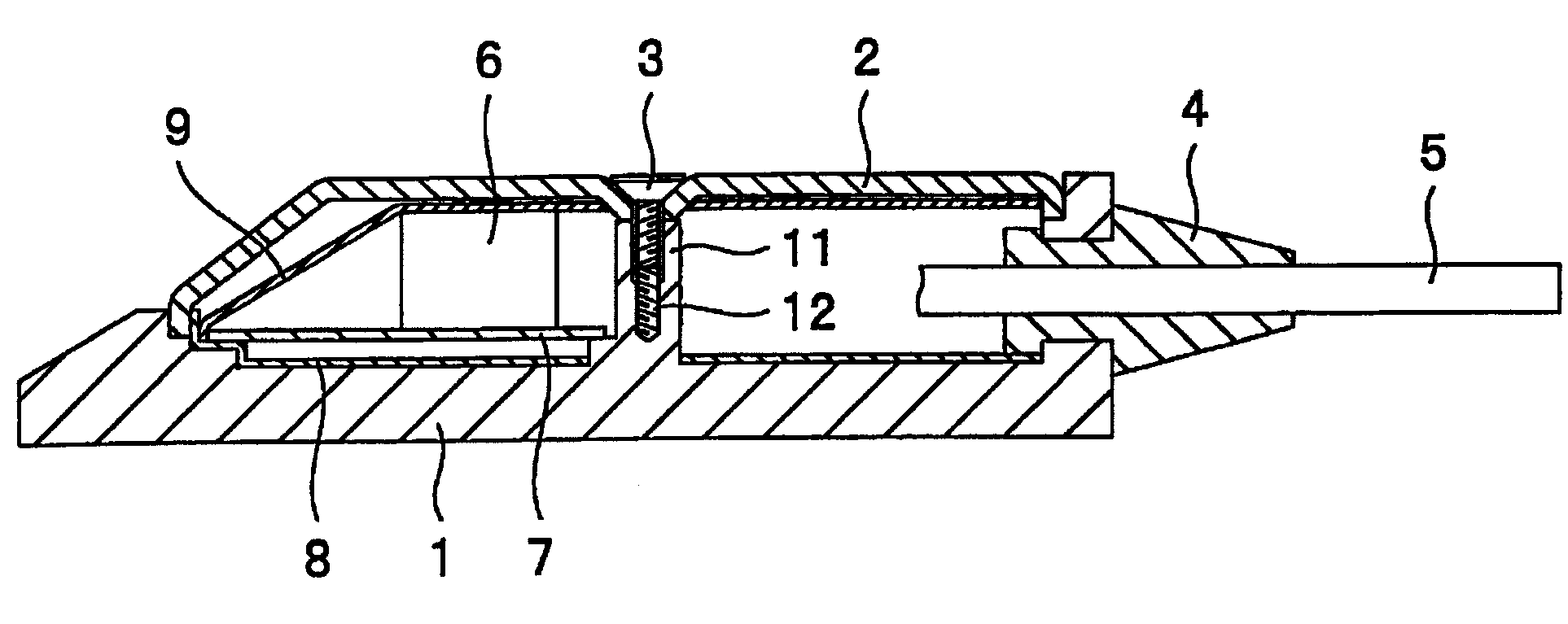
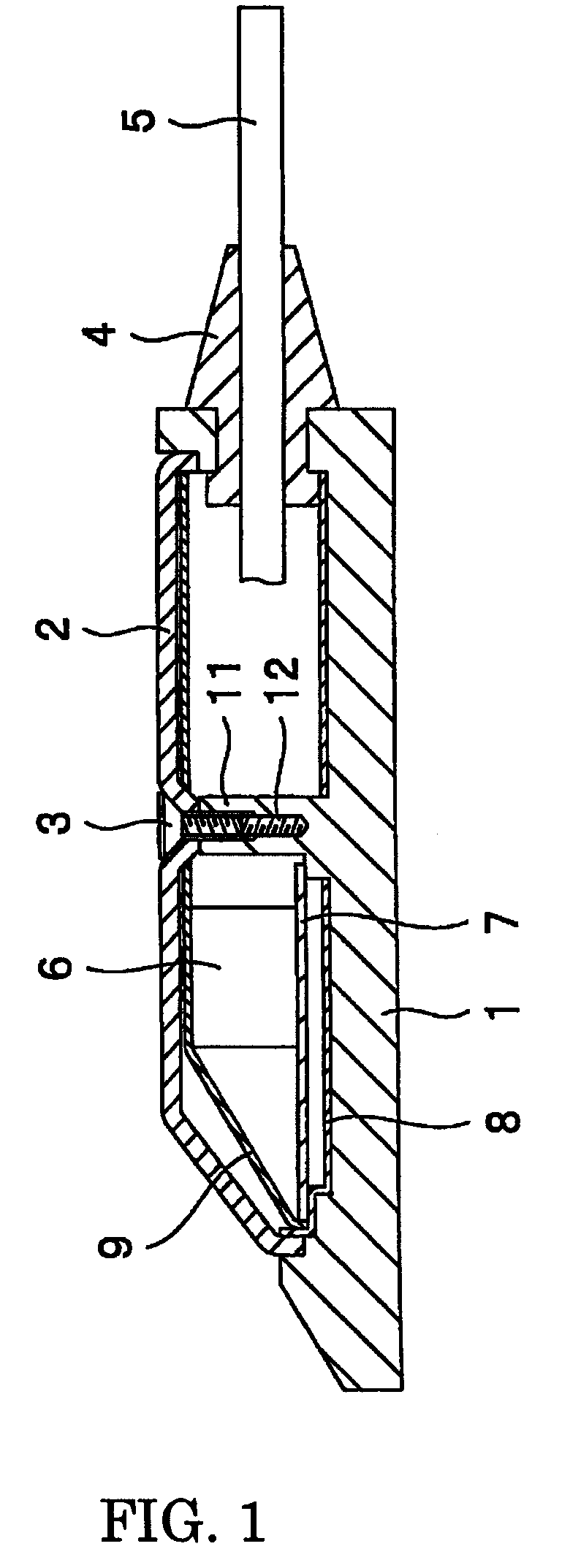
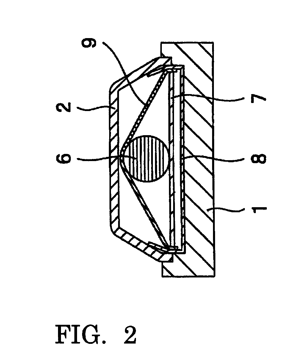
[0020]In FIG. 1 and FIG. 2, reference numeral 1 denotes a base of the boundary microphone. The base 1 is also called a boundary plate, and is made of a flat metal, and can be secured to a desk top or a floor surface. In an upper surface of the base 1, a cavity (dimple) for mounting the later-described circuit board and the like is formed. From the upper surface of the base 1, a column 11 for connecting the later-described cover 2 is erected by integral molding, approximately in the center when viewing the base 1 from the plane direction. In the column 11, a tapped hole 12 is formed from the upper end. For the base 1, the left side in FIG. 1 is the front side and the right side is the backside, and a wall is integrally formed at the back end of the base 1, and a bush 4 is fitted into a hole that is formed through this wall. In t...


PUM


Abstract

A boundary microphone, comprising: a base made of a metal; a cover made of a metal having a plurality of holes for introducing sound waves; and internal components including a microphone unit that is disposed in an internal space enclosed by the base and the cover; a first metallic part disposed on one side of the upper and lower sides of the internal components; and a second metallic part, which is disposed on other side of the upper and lower sides of the internal components and which encloses the internal components along with the first metallic part from all directions, are provided, wherein the base, the cover, the first metallic part, and the second metallic part are alternately overlapped at their peripheral portions, and wherein at least one of the first metallic part and the second metallic part is made of a metallic mesh.

Description

BACKGROUND OF THE INVENTION[0001]1. Field of the Invention[0002]The present invention relates to a boundary microphone, and in particular to the boundary microphone characterized by its shielding structure.[0003]2. Related Background of the Invention[0004]A flat microphone to be installed on a desk or the like for use is an on-surface sound pickup microphone, and is called a boundary microphone or a surface mount microphone. In the present invention, a microphone of such a type is referred to as a “boundary microphone”. Since the boundary microphone is intended to be installed in a low profile manner on a desk or the like, the boundary microphone is designed so as to be flat with restricted height. Usually, the boundary microphone has a structure in which a metallic part having a plurality of openings for introducing sound waves is connected, one above the other, with a metallic part for supporting a microphone unit and an electronic circuit board. The microphone unit and the electr...

Claims


Application Information

Patent Timeline
IPC IPC(8): H04R11/04
CPCH04R11/04
Inventor YOSHINO, SATOSHI
Owner AUDIO-TECHNICA
Learn More