

Filter for optical recording medium, optical recording medium, method for producing the same, optical recording method and optical reproducing method
- Summary
- Abstract
- Description
- Claims
- Application Information
AI Technical Summary
Benefits of technology
Problems solved by technology
Method used
Image

Examples
first embodiment
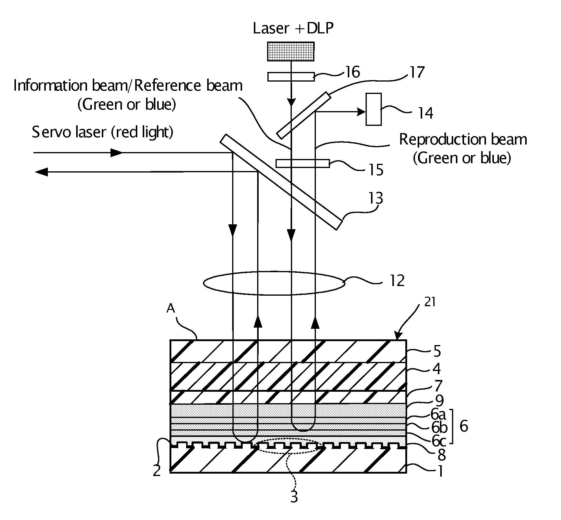
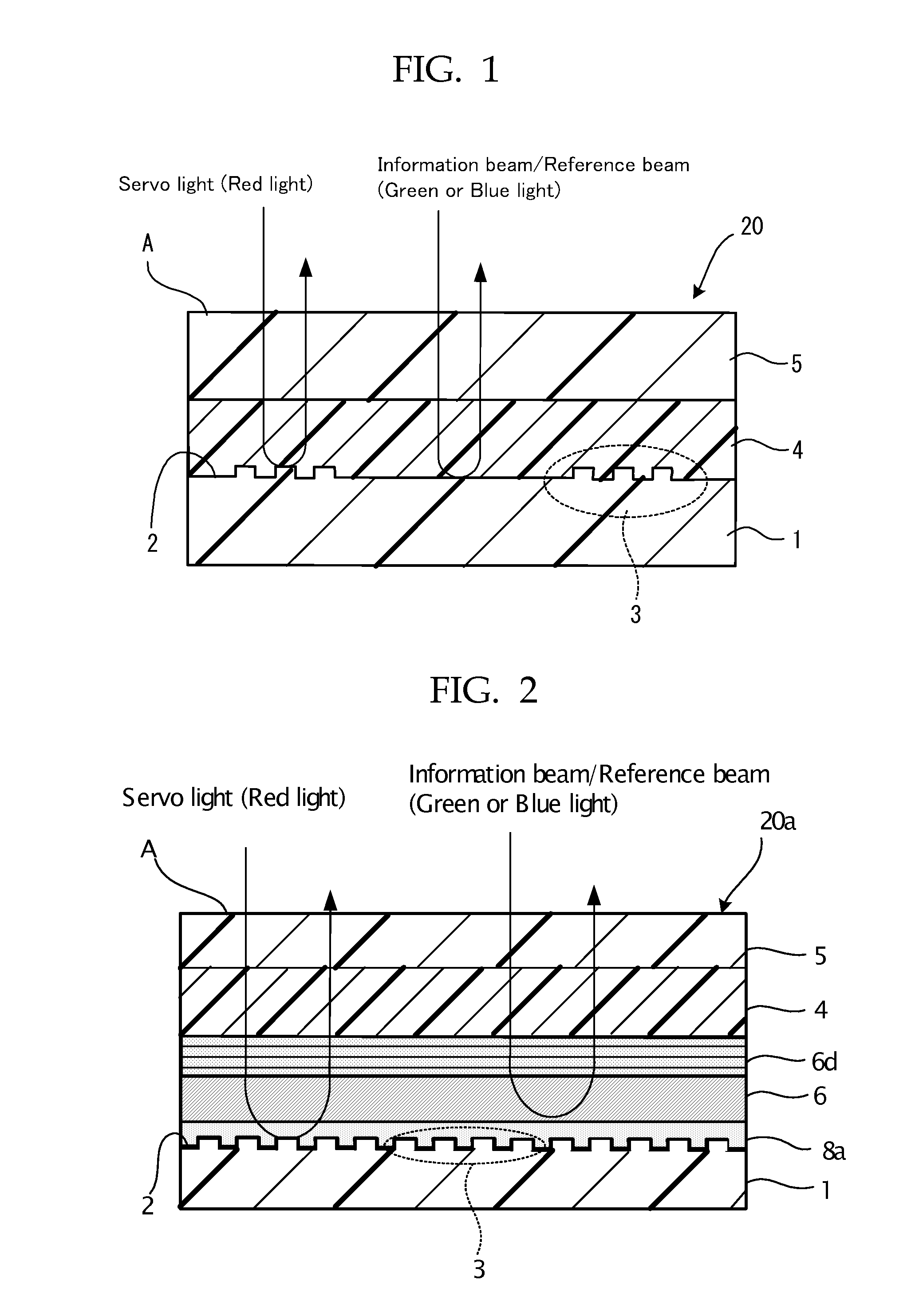
[0225]FIG. 7 is a schematic sectional view showing the configuration of the optical recording medium in a first embodiment of the present invention. In this optical recording medium 21 according to the first embodiment, a servo pit pattern 3 is formed on a second substrate 1 made from a polycarbonate resin or a glass, and a reflective film 2 is formed by coating with aluminum, gold or platinum on the servo pit pattern 3. In FIG. 7, the servo pit pattern 3 is formed on the entire surface of a second substrate 1, but as shown in FIG. 1, the servo pit pattern may be formed periodically. The height of this servo pit is 1750 angstroms (175 nm) in maximum, which is sufficiently small compared with the thickness of other layers including the second substrate.
[0226]A first gap layer 8 is formed by coating the material such as ultraviolet curable resin on the reflective film 2 formed on the second substrate 1 by spin coating. The first gap layer 8 is effective for protecting the reflective f...
second embodiment
[0235]FIG. 8 is a schematic view showing the configuration of the optical recording medium in a second embodiment of the present invention. In an optical recording medium 22 according to the second embodiment, a servo pit pattern 3 is formed on a second substrate 1 made of polycarbonate resin or glass, and the serve pit pattern 3 is coated with Al, Au, Pt or the like to form a reflective film 2. The height of the servo pit pattern 3 is generally 1750 angstrom (175 nm), as in the case of the first embodiment.
[0236]The second embodiment differs from first embodiment in that the optical recording medium 22 has a second gap layer 7 disposed between an optical compensation layer 9 and a recording layer 4.
[0237]The filter layer 6 which is a laminate of three cholesteric liquid crystal layers is formed on a first gap layer 8 after the first gap layer 8 is formed, and the same filter layer as in the first embodiment can be used.
[0238]In the second gap layer 7 there is a point at which both ...
example 1
Production of Laminate of Optical Compensation Layer
—Production of Support—
[0276]A cellulose triacetate film (Fujitac manufactured by Fuji Photo Film Co., Ltd.) was used as a support which was used in a laminate of an optical compensation layer. The cellulose triacetate film had a thickness of 60 μm, a retardation (Re) of 3 nm, and a retardation (Rth) of 40 nm.
[0277]Each of the retardations was measured by an automatic birefringence analyzer (KOBRA 21DH manufactured by Oji Scientific Instruments) and calculated.
—Preparation of Coating Solution for Optical Compensation Layer—
[0278]Next, 3.8 g of a rod-shaped liquid crystal compound expressed by the following Structural Formula (1), 0.06 g of a photoinitiator (Irgacure 907 manufactured by Ciba-Geigy K.K), 0.02 g of a sensitizer (Kayacure DETX manufactured by Nippon Kayaku Co., Ltd.), and 0.002 g of an air-interface vertically aligning agent expressed by the following Structural Formula (2) was dissolved in 9.2 g of methyl ethyl ketone...
PUM
 Abstract
Description
Claims
Application Information