Boundary microphone

Inactive Publication Date: 2010-12-23
AUDIO-TECHNICA
View PDF32 Cites 4 Cited by
  • Summary
  • Abstract
  • Description
  • Claims
  • Application Information

AI Technical Summary

Benefits of technology

[0015]With the present invention, the metal mesh and the base made of metal can be connected without any gap. Thus electromagnetic waves that are to enter the internal components from outside can be more effectively blocked. Even if a mobile phone is u

Problems solved by technology

There is a problem that the electromagnetic waves having a short wavelength can enter the internal space of a micro

Method used


Image

  • Boundary microphone
  • Boundary microphone
  • Boundary microphone

Examples


Example

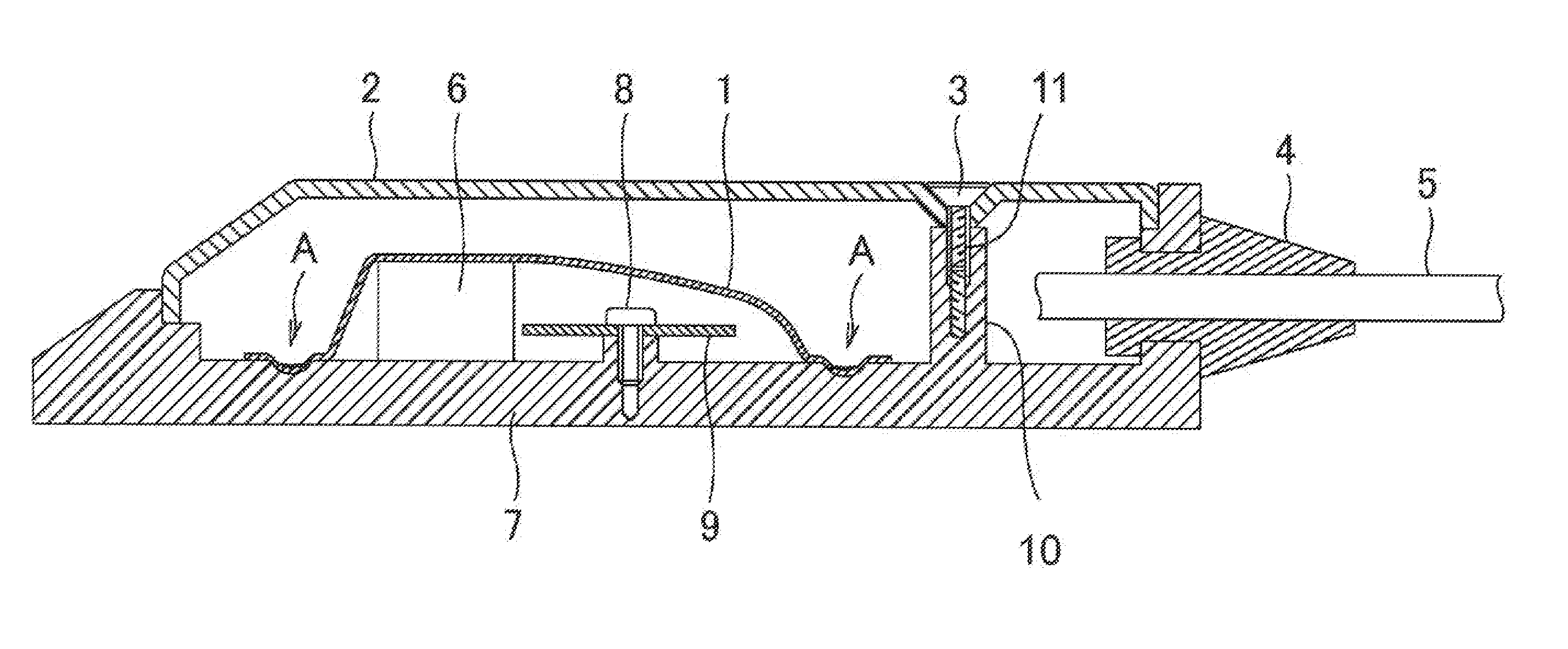
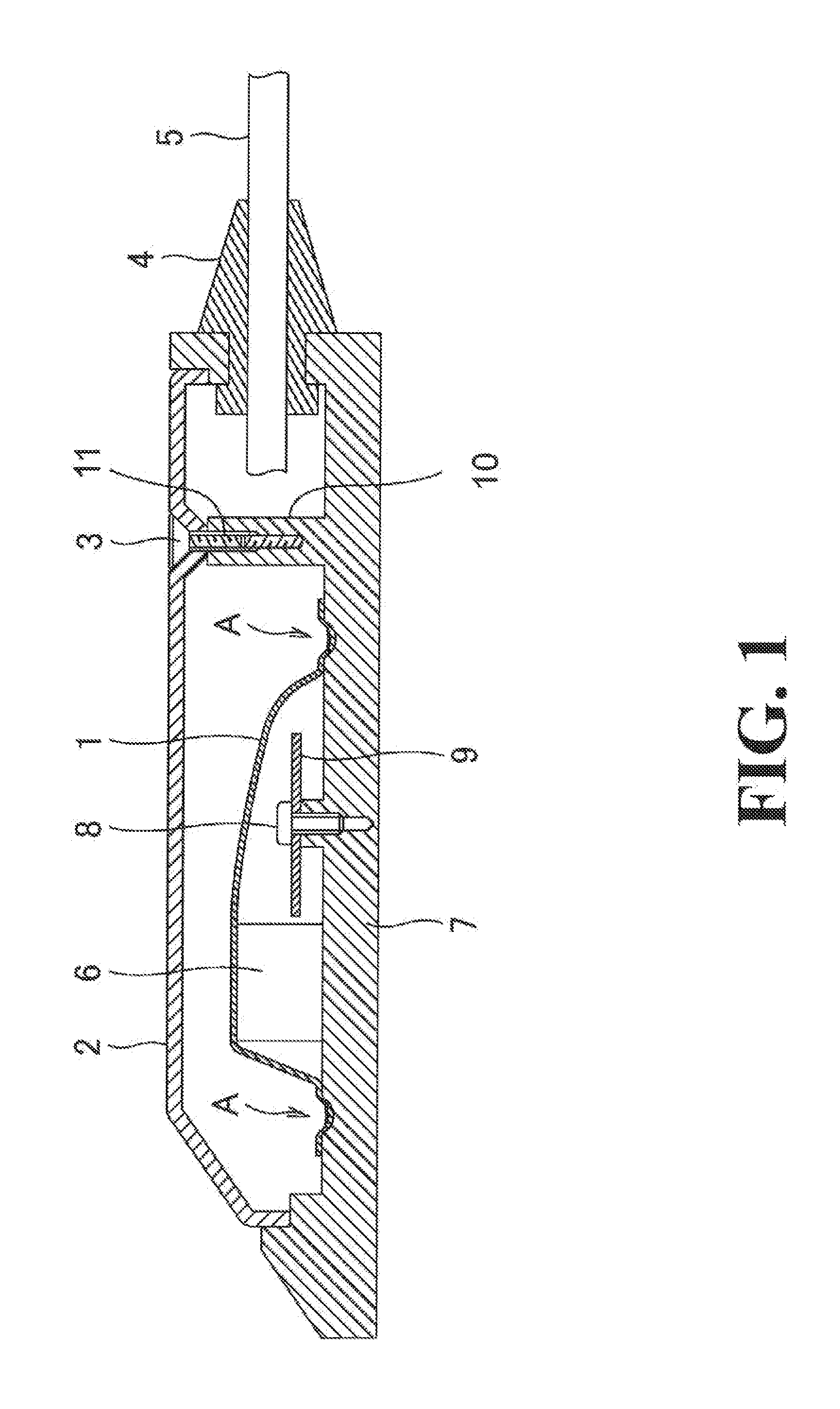
[0021]An embodiment of a boundary microphone according to the present invention is described below with reference to some of the drawings.

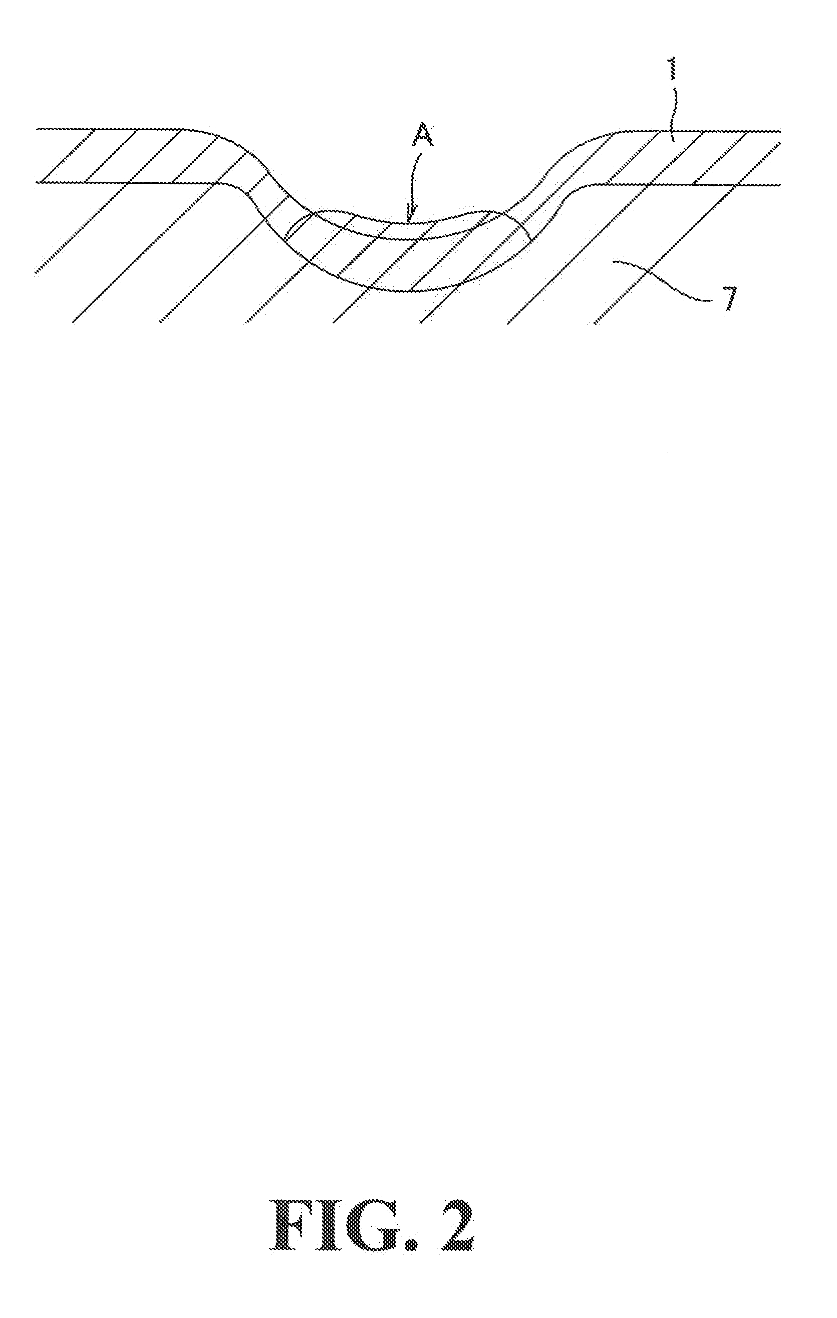
[0022]As illustrated in FIG. 1, this boundary microphone includes: a metal mesh 1; a microphone cover 2; a male screw 3; a cord bush 4; a microphone cord 5; a microphone unit 6; a base 7; a fixing screw 8; and a circuit board 9. The metal mesh 1 protects the microphone unit 6 from electromagnetic waves. The microphone cover 2 is made of metal, has a large number of openings (sound wave introduction holes), and is attached on the base 7. The base 7 has a flat shape with a restricted height and the upper surface side thereof is opened. The circuit board 9 is fixed with the screw 8. The microphone unit 6 may be incorporated while being installed on the circuit board 9. Alternatively, the microphone unit 6 may be incorporated separately from the circuit board 9. In an upper surface of the base 7, a hollow for mounting the circuit board 9 and the like ...


PUM


Abstract

A boundary microphone includes: a metal mesh; a base made of metal; a cover made of metal on which a plurality of holes through which a sound wave is passed is formed; and a microphone unit that is installed on the base and converts sound into an electrical signal. The metal mesh is welded onto the base with a metal material of the base entering a space of the metal mesh. The microphone unit is covered by the metal mesh.

Description

BACKGROUND OF THE INVENTION[0001]1. Field of the Invention[0002]The present invention relates to a boundary microphone that is mainly placed on a desk upon use, and more specifically to a boundary microphone including a metal mesh to improve a shielding effect against electromagnetic waves.[0003]2. Description of the Related Art[0004]Boundary microphones are known that are mainly placed on a desk upon use. FIG. 5 illustrates an example of a conventional boundary microphone. A base 17 of the boundary microphone illustrated in FIG. 5 is formed of a flat piece of metal and can be fixed on a surface of a desk or a floor. In an upper surface of the base 17, a cavity (hollow) for mounting a circuit board 18 and the like is formed. From the upper surface of the base 17, a column 21 integrally formed with the base 17 is erected, approximately in the center when viewing the base 17 from the plane direction. A later described cover 20 is connected to the base 17 via the column 21. In the colu...

Claims


Application Information

Patent Timeline
IPC IPC(8): H04R11/04
CPCH04R1/086
Inventor AKINO, HIROSHI
Owner AUDIO-TECHNICA
Why Eureka
Try Eureka