Floor panel

Inactive Publication Date: 2006-07-13
AKZENTA PANEELE PROFILE GMBH
View PDF9 Cites 21 Cited by
  • Summary
  • Abstract
  • Description
  • Claims
  • Application Information

AI Technical Summary

Benefits of technology

[0035] The effect of the intermediate joint can be further improved by the provision of a coating on the surface of the groove of the imitation intermediate joint. The visual appearance of the coating can be matched to the decorative layer of the duty layer arrangement. A possible way of achieving that provides that the groove is produced prior to application of the decorative layer and, in an additional working step, after application of the duty layer arrangement with the decorative layer, the duty layer arrangement in the region of

Problems solved by technology

Because of the particular structure of the wood imitation by means of synthetic resin, the construction of the known floor panel is complicated and costly to produce.
The use of the resin-impregnated layers is costly and, as is generally known, problematical for the reason that resin impregnation of the printed paper with a hot liquid wax causes a growth in the length and the width of the paper.
The complexity involved in the processing of resin and paper increases the reject rate in the manufacture of the resin-impregnated printed paper.
Papers that are less than or exceed the target size cannot be used for the production of a floo

Method used


Image

  • Floor panel
  • Floor panel
  • Floor panel

Examples


Embodiment Construction

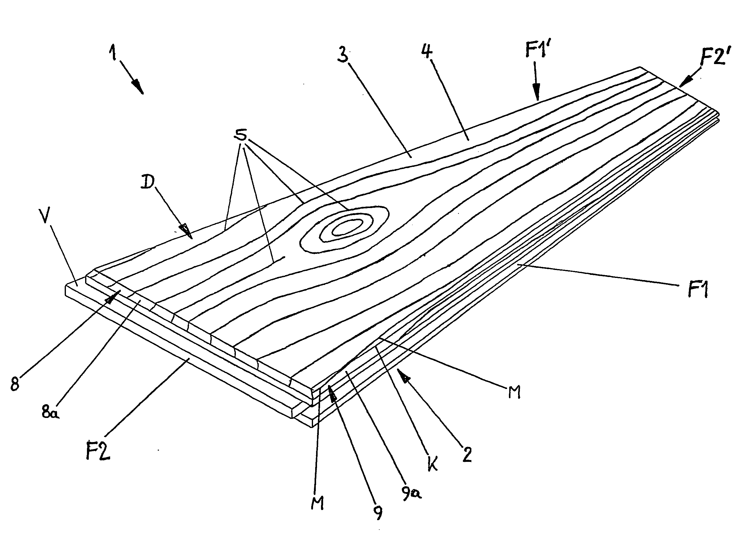
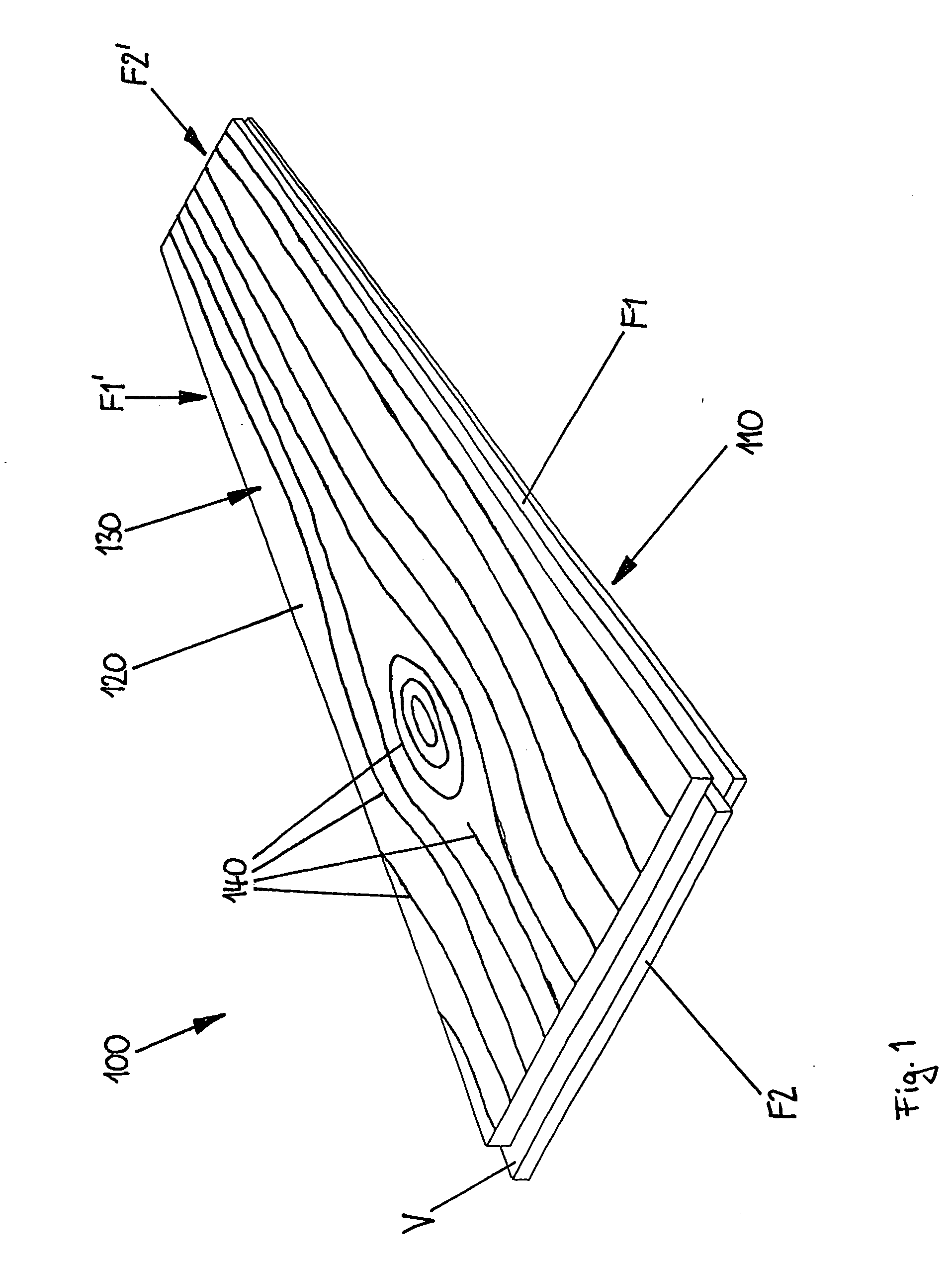
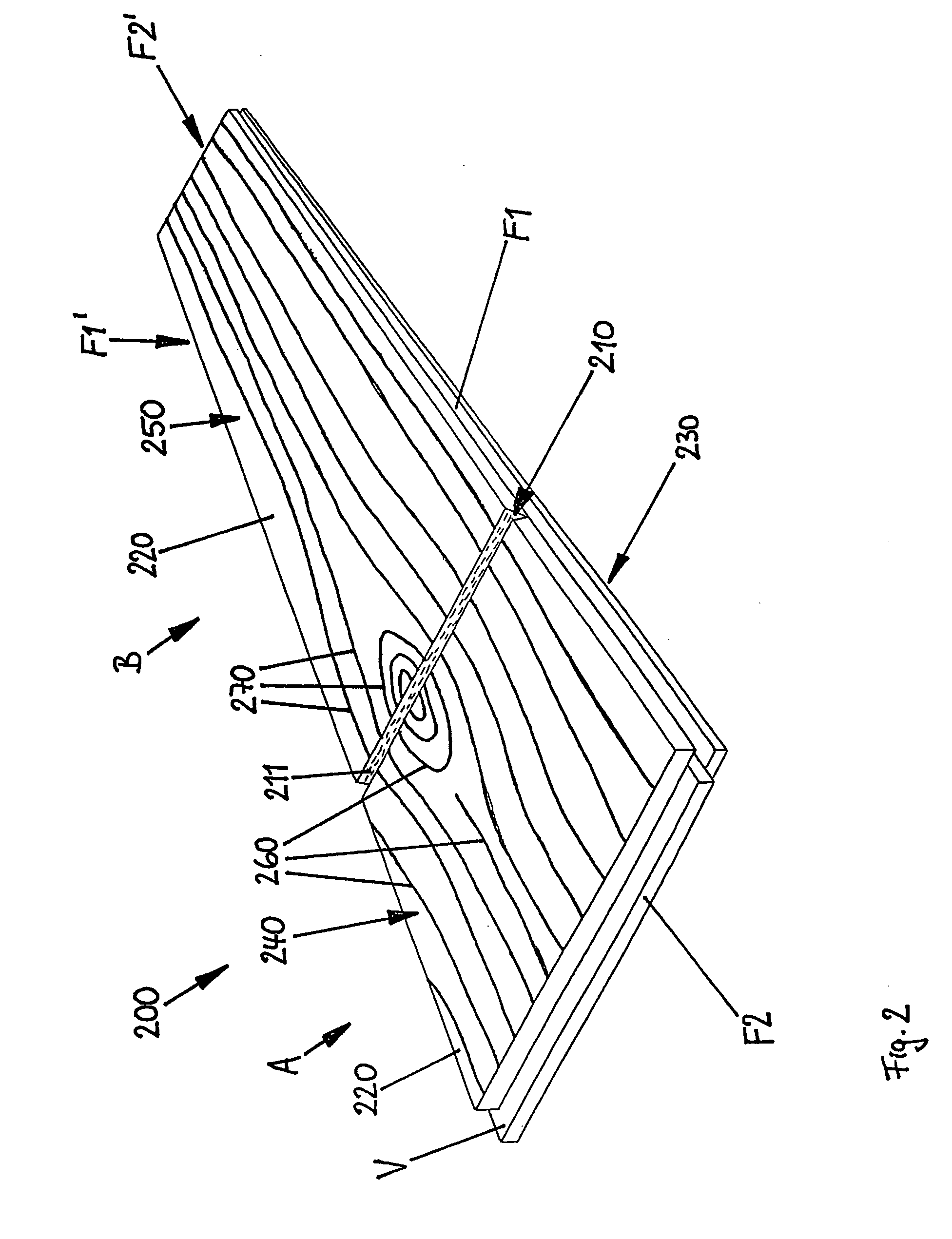
[0053] FIGS. 1 to 4 show floor panels without obtuse edges. FIGS. 5 to 9 show floor panels with obtuse edges. An obtuse edge involves removal of material at a side edge portion of a top side of the floor panel. The removal of material results in the formation of a protection surface, which makes the side edge portion of the floor panel less susceptible to damage.

[0054] Respective edge locking profiles are illustrated at each of the edges of all floor panels in FIGS. 1 to 9. Arranged at the oppositely disposed edges are respective corresponding edge locking profiles F1, F1′ and F2, F2′. A plurality of those floor panels can be joined by means of the edge locking profiles F1, F1′ and F2, F2′ to afford a floor surface because further floor panels can be locked to a floor panel at all sides. The edge locking profiles F1, F1′ and F2, F2′ are shown in FIGS. 1 to 9 by way of example in the form of tongue-and-groove profiles which have an elastically bendable locking means V and V1, V2, re...


PUM

PropertyMeasurementUnit
Electrical resistanceaaaaaaaaaa
Adhesivityaaaaaaaaaa
Transparencyaaaaaaaaaa

Abstract

The invention concerns a floor panel (1) comprising a carrier panel portion (2) that is provided at a top side with a duty layer arrangement (3), which duty layer arrangement (3) is provided with a decorative representation, wherein provided in the duty layer arrangement (3) is an anti-wear means (66), and edge locking profiles (F1, F1′, F2, F2′) at at least two mutually opposite edges of the floor panel (1), wherein at least one edge locking profile (1) has at least one elastically bendable locking means (V), wherein the decorative representation is covered with a transparent lacquer layer (65) and that the anti-wear means (66) is provided in the lacquer layer (65).

Description

BACKGROUND OF THE INVENTION [0001] 1. Field of the Invention [0002] The invention concerns a floor panel comprising a carrier panel portion that is provided at a top side with a duty layer arrangement, which duty layer arrangement has a decorative representation, wherein an anti-wear means is provided in the duty layer arrangement, and edge locking profiles at at least two mutually opposite edges of the floor panel, wherein at least one edge locking profile has at least one elastically bendable locking means. [0003] 2. Description of the Background [0004] A floor panel of the general kind set forth is known from FIG. 3 of WO 01 / 96689 A1. The known floor panel has a groove-and-tongue connection with an undercut configuration that is intended to prevent joined floor panels from moving away from each other. The walls of the groove project from the edge of the floor panel by differing distances. That groove wall, which projects further from the edge of the floor panel, forms the elastic...

Claims


Application Information

Patent Timeline
IPC IPC(8): E04C3/00
CPCB32B3/06B32B3/30B32B7/02B32B21/04B32B2255/08B32B2255/26B32B2260/026B32B2307/554B32B2419/04B44C5/0476B44F9/02B44F11/04E04F15/02E04F15/02033E04F15/04E04F2201/0115E04F2201/0153
Inventor EISERMANN, RALF
Owner AKZENTA PANEELE PROFILE GMBH
Why Eureka
Try Eureka