Degassing centrifugal apparatus, process for pumping and degassing a fluid and process for producing paper or board

Inactive Publication Date: 2004-12-07
POM TECH
View PDF32 Cites 17 Cited by
  • Summary
  • Abstract
  • Description
  • Claims
  • Application Information

AI Technical Summary

Benefits of technology

A preferred embodiment of the process is provided by connecting the gas discharge to a vacuum source which may be used either to improve the effect of gas separation in the pump, o

Problems solved by technology

The exact place of the hydraulic jump varies with the flow conditions and the shape of the air separation

Method used


Image

  • Degassing centrifugal apparatus, process for pumping and degassing a fluid and process for producing paper or board
  • Degassing centrifugal apparatus, process for pumping and degassing a fluid and process for producing paper or board
  • Degassing centrifugal apparatus, process for pumping and degassing a fluid and process for producing paper or board

Examples


Example

In the following detailed description of the invention reference is made to the drawings, wherein the same numerals are used for the same or functionally similar parts. It is to be noted that the present pump operates largely in the same manner as the one described in the above mentioned U.S. Pat. No. 5,861,052. Reference is made to the detailed description in said patent, it being clear to those skilled in the art that the many variations in the general construction and operation of the prior art pump are applicable to large extent also to the pump according to the present invention.

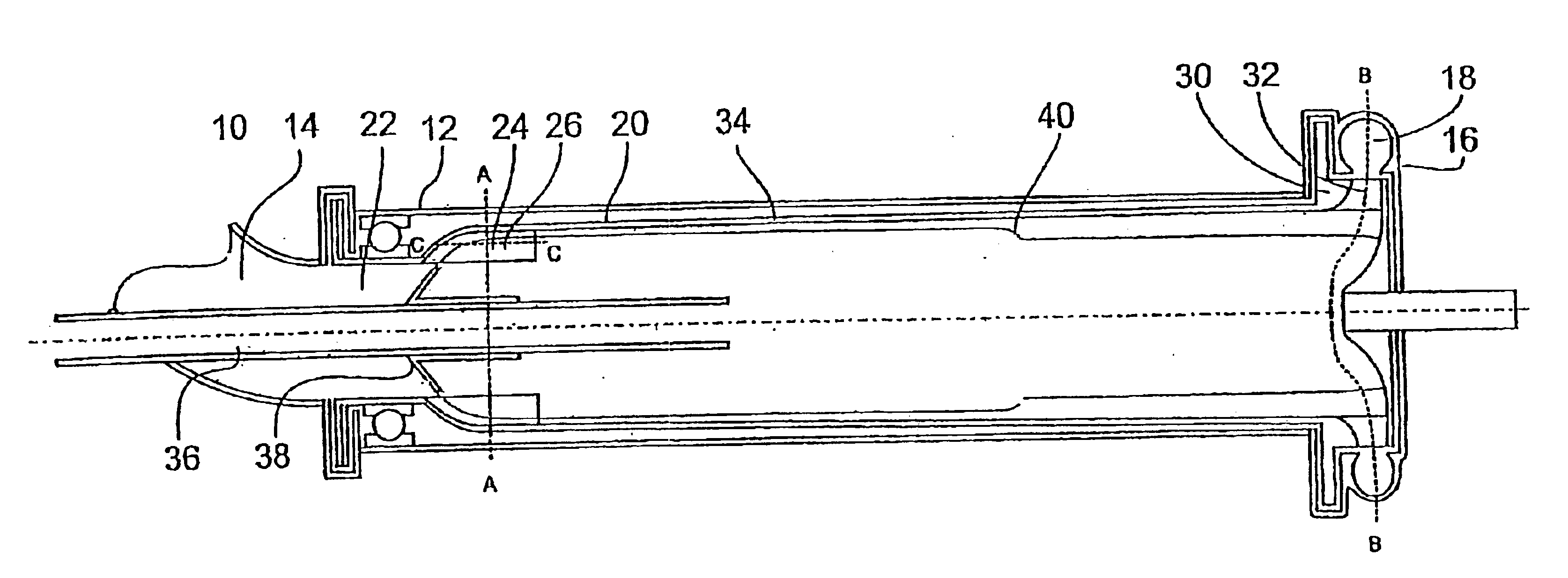
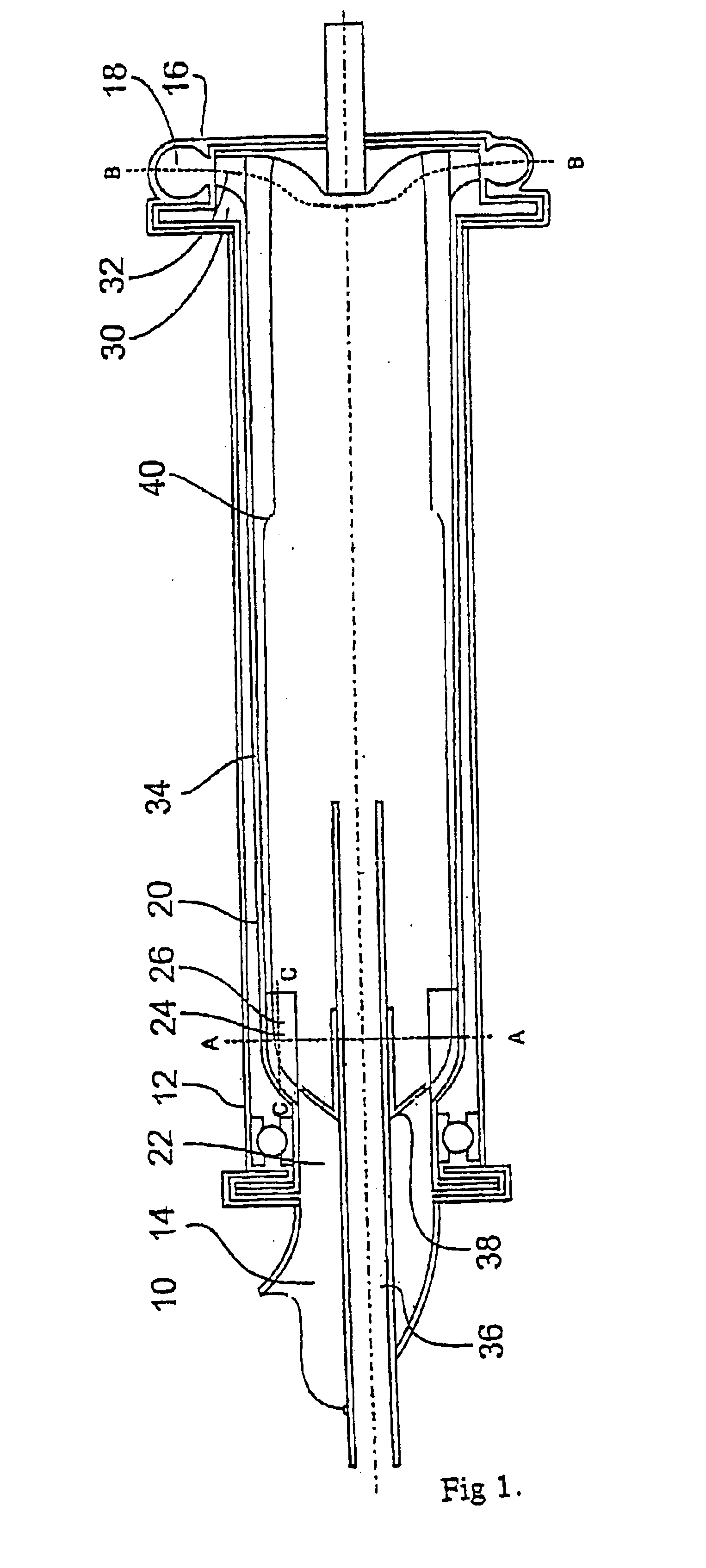
In the embodiment of the invention according to FIG. 1 the degassing pump 10 according to the invention comprises a stationary hollow tubular housing 12 with a stationary inlet pipe 14 at one end a stationary outlet spiral 16 with an outlet pipe 18 at the opposite end. Inside the housing 12 there is a hollow rotor 20 rotatably mounted in bearings. The housing 12 forms a closed space around the rotor 20....


PUM

PropertyMeasurementUnit
Pressureaaaaaaaaaa
Angleaaaaaaaaaa
Centrifugal forceaaaaaaaaaa

Abstract

The invention relates to a degassing centrifugal apparatus such as a pump and to a process for pumping and degassing a fluid. The apparatus has a rotatable hollow rotor connected to a stationary fluid inlet at one end and a stationary liquid outlet at the opposite end and a gas exhaust in the center thereof. The rotor has at its inlet end a bladed wheel with arcuate blades. The bladed wheel accelerates a fluid flow in said rotor inlet end and causes the fluid to rotate at a peripherical velocity higher than the peripherical velocity of said rotor inlet end. The apparatus is especially useful for pumping and degassing backwater in the production of paper or board in a paper machine.

Description

1. Technical Field of the InventionThe present invention relates to a degassing centrifugal apparatus such as a pump and to a process for degassing and pumping a liquid, especially backwater in the production of paper or board in a paper machine.2. Prior ArtBackwater drained through a forming fabric in a papermaking process, normally, contains a large amount of entrained air. Since the short circulation of a paper machine requires a particularly constant flow, disturbing air is normally removed by conducting the drained backwater, by means of special pipe or channel systems, from the dewatering elements to an open backwater tank. The deaerated water is then pumped back to the fiber process of the short circulation preceding sheet forming. Other liquids which require air free pumping are, among others, black liquor, deinking sludge and stock, coating colour, etc.Pumps, which are able to separate gas from a fluid to be pumped are well known as such, but the objective of such pumps is ...

Claims


Application Information

Patent Timeline
IPC IPC(8): B01D19/00D21D5/00D21D5/26F04D13/04F04D13/02F04D3/02F04D7/00F04D3/00F04D7/04F04D29/22F04D29/18
CPCB01D19/0052D21D5/26F04D3/02F04D13/043F04D29/181F04D29/2288F04D7/04Y10S417/90Y02P70/10
Inventor MEINANDER, PAUL
Owner POM TECH
Why Eureka
Try Eureka