Adaptive cooling unit for a power tool

Inactive Publication Date: 2010-04-29
AEG ELECTRIC TOOLS
View PDF8 Cites 18 Cited by
  • Summary
  • Abstract
  • Description
  • Claims
  • Application Information

AI Technical Summary

Benefits of technology

[0018]Finally, it is advantageous that the torque transfer means comprises a transmission so that the fan wheel rotates at a higher speed than the armature shaft. Due to the increased air thr

Problems solved by technology

Too high a motor temperature may have the result that the power tool cannot be operated for a certain time during which the motor has t

Method used


Image

  • Adaptive cooling unit for a power tool
  • Adaptive cooling unit for a power tool
  • Adaptive cooling unit for a power tool

Examples


Example

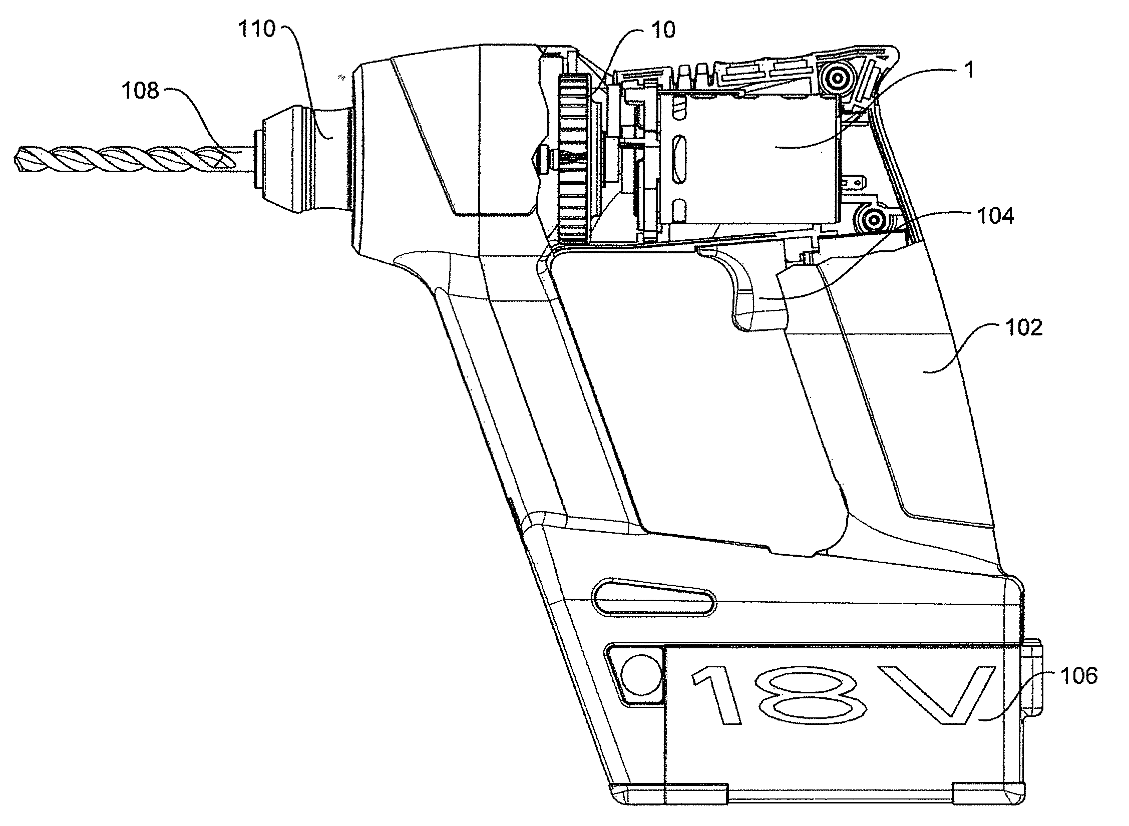
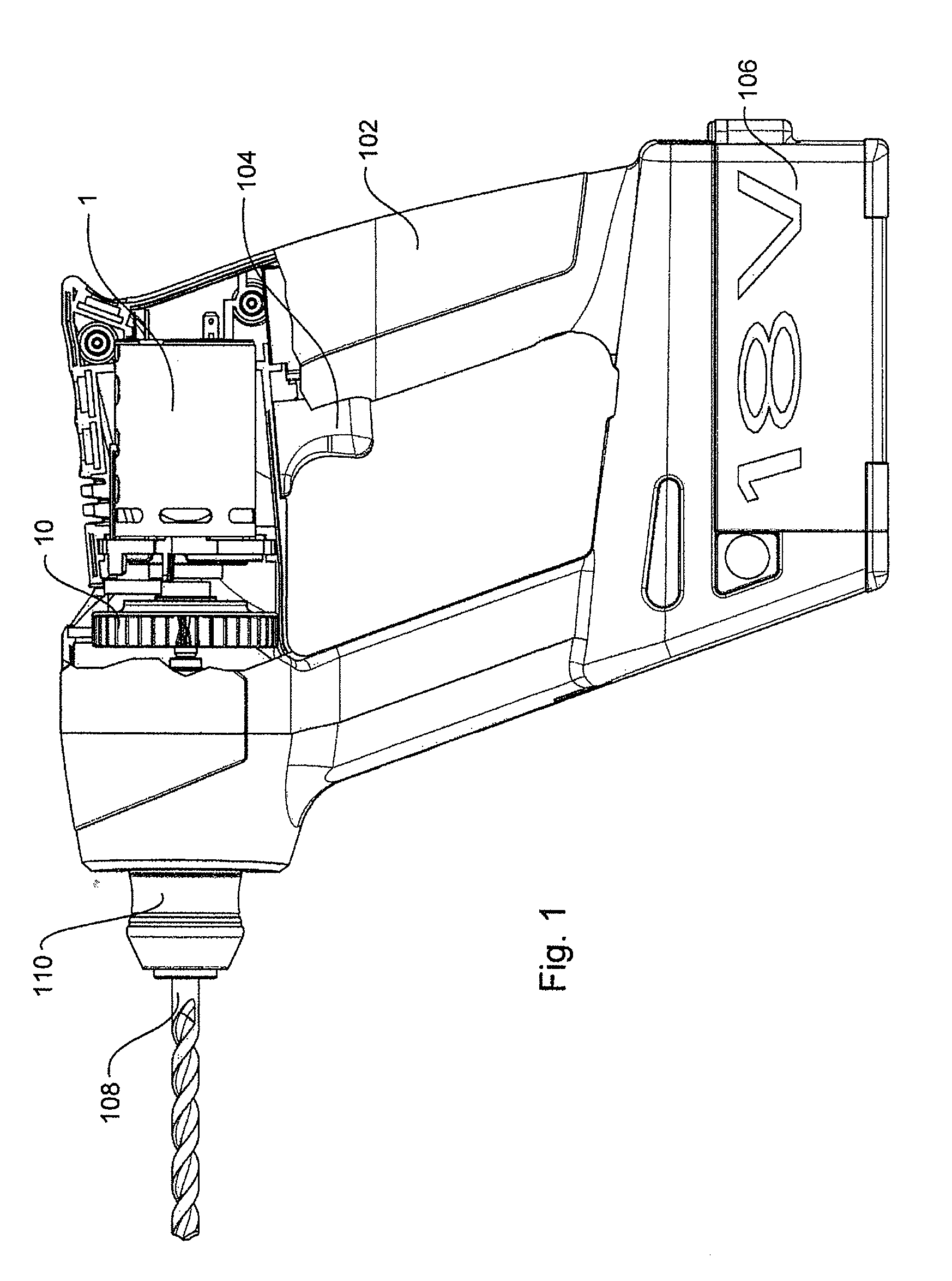
[0024]FIGS. 1 to 4 show, as preferred embodiment of the invention, an electrical power drill having a cooling unit according to the invention.

[0025]As can be seen from FIG. 1, the power drill as such is configured in a known manner and comprises a housing having a handle 102, an operating switch 104 and a battery pack 106. In the housing there is a motor 1 for driving a drill tool 108 held in a tool fitting 110. To that end, a gear not shown in more detail is provided in a conventional manner between a shaft of the motor 1 and the drill tool 108.

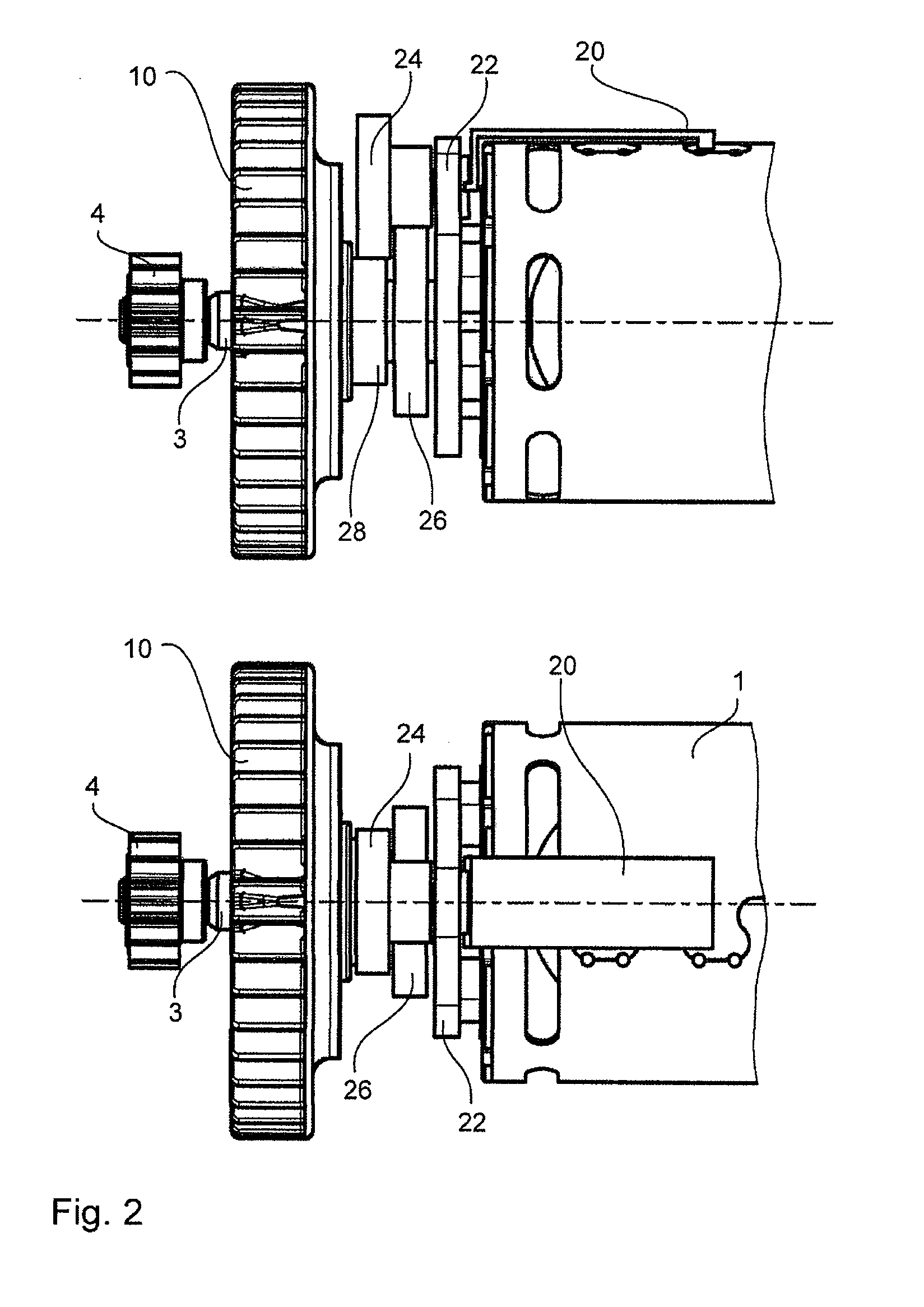
[0026]Moreover, a cooling unit having a fan wheel 10 and described in the following in more detail by reference to FIGS. 2 to 4, is arranged in the housing for cooling the engine 1.

[0027]The fan wheel 10 is floatingly supported on an armature shaft 3 of the power drill by means of a floating bearing having an inner ring 32 and an outer ring 28. On its part, the armature shaft 3 is connected to the motor shaft 2 and rotates along with it. At ...


PUM


Abstract

A cooling unit for a power tool comprises a fan wheel (10) to be supported on an armature shaft (3) of a motor (1) of the power tool. The cooling unit comprises a torque transfer means as well as an actuating means (20, 22) for actuating this torque transfer means so as to selectively transfer the rotation of the armature shaft (3) to the fan wheel (10) during operation of the power tool.

Description

FIELD OF THE INVENTION[0001]The present invention concerns an adaptive cooling unit for a power tool as well as a power tool having such an adaptive cooling unit.PRIOR ART[0002]The durability and operational readiness of the motor of power tools such as portable drills, hammer drills, thread cutters, power screwdrivers, grinders or the like crucially depend on motor temperature. Too high a motor temperature may have the result that the power tool cannot be operated for a certain time during which the motor has to cool down. Therefore, during operation, the temperature of the motor should not exceed a certain value.[0003]Hence, power tools usually have an incorporated fan that serves for cooling the motor and possible further components of the power tool, for example the transmission and various electronic components.[0004]The motor temperature increases all the more the higher is the load torque to be applied by the motor. In contrast, the temperature drops if the motor is in no-loa...

Claims


Application Information

Patent Timeline
IPC IPC(8): H02K9/06
CPCB25F5/008H02K9/06H02K7/145
Inventor LANGE, MICHAELVOGLER, RAINER
Owner AEG ELECTRIC TOOLS
Why Eureka
Try Eureka