Electric power steering apparatus

Inactive Publication Date: 2007-08-23
JTEKT CORP
View PDF2 Cites 5 Cited by
  • Summary
  • Abstract
  • Description
  • Claims
  • Application Information

AI Technical Summary

Benefits of technology

[0011]According to the present mode, by an elastic body used as the outer ring or the inner ring, a preload is given to the rolling element so that an internal bearing gap can be eliminated. As a result, occurrence of noise due to a collision of the inner ring and the outer ring against the rolling ele

Problems solved by technology

However, a gap exists among the inner ring, the outer ring and the rolling elements, and due to the gap, there is a problem that noise occurs as a result of the rolling element colliding against th

Method used


Image

  • Electric power steering apparatus
  • Electric power steering apparatus
  • Electric power steering apparatus

Examples


Example

[0016]Hereinafter, embodiments of the present invention will be described in detail with reference to the drawings.

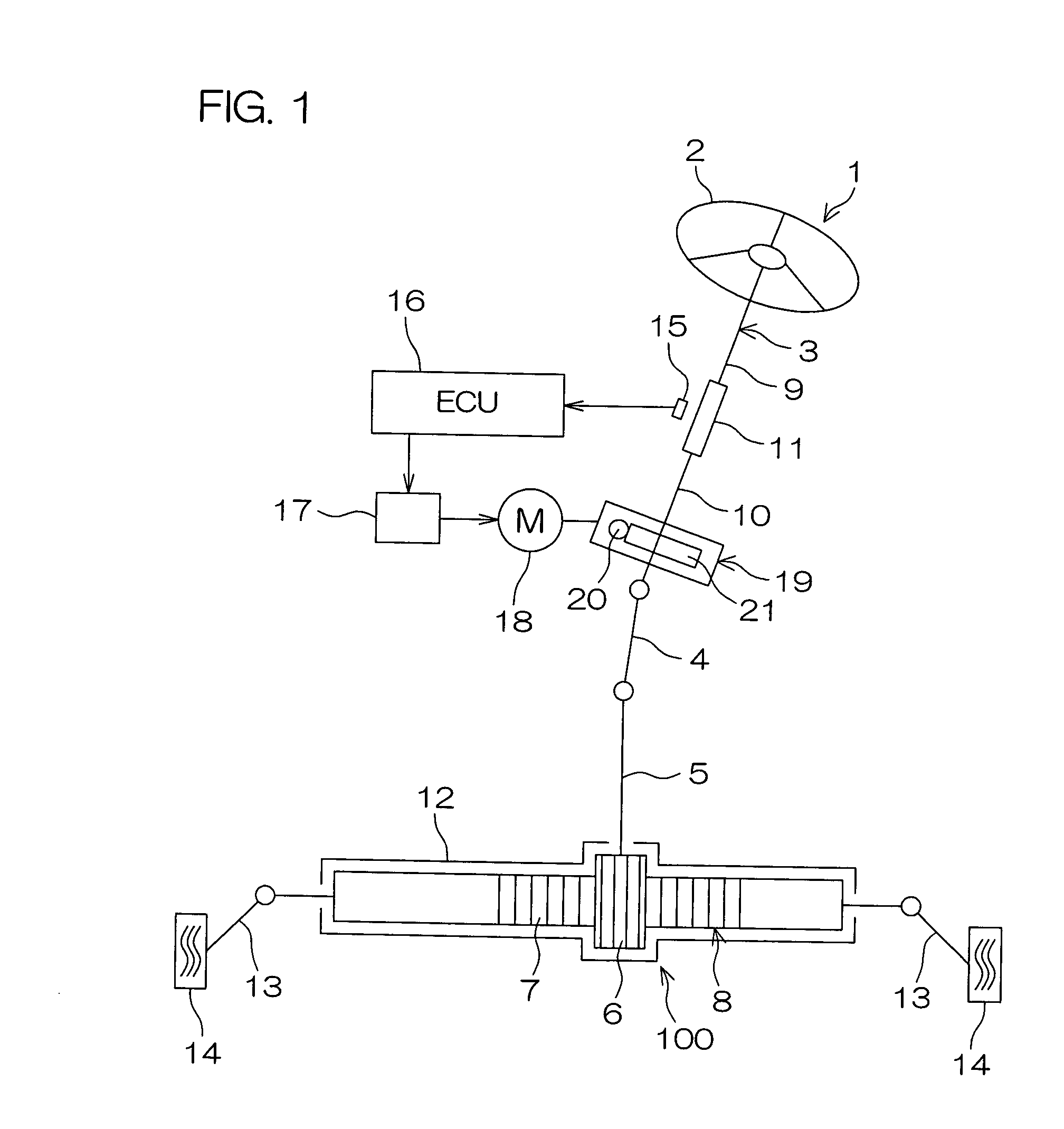
[0017]FIG. 1 is a schematic view showing a schematic configuration of an electric power steering apparatus 1 of an embodiment of the present invention. Referring to FIG. 1, the electric power steering apparatus 1 comprises a steering shaft 3 coupled to a steering member 2 such as a steering wheel, a pinion shaft 5 coupled to the steering shaft 3 via an intermediate shaft 4, and a rack bar 8 having a rack 7 engaged with a pinion 6 formed on the pinion shaft 5 and being a turning shaft extending in the left and right direction of an automobile. The pinion shaft 5 and the rack bar 8 form a rack and pinion mechanism 100 as a steering mechanism.

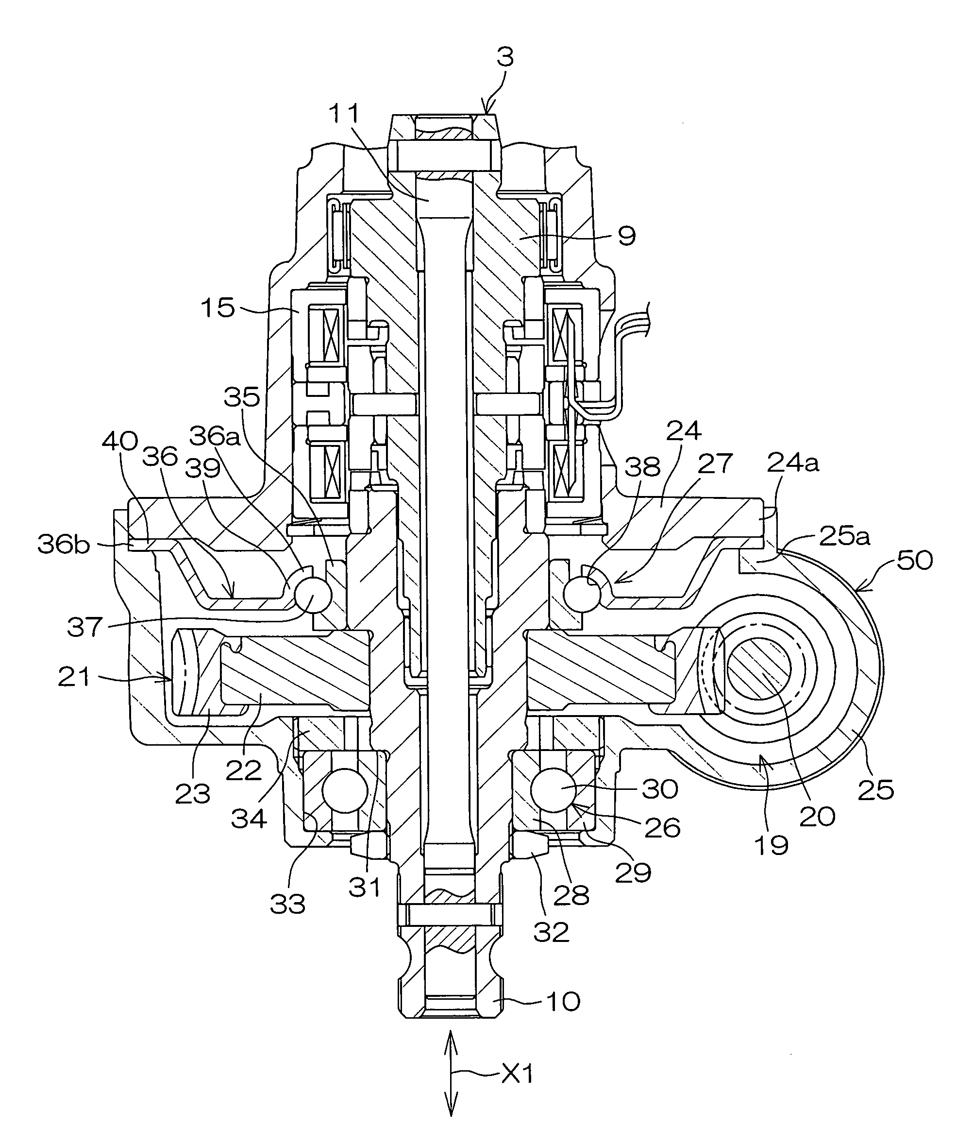
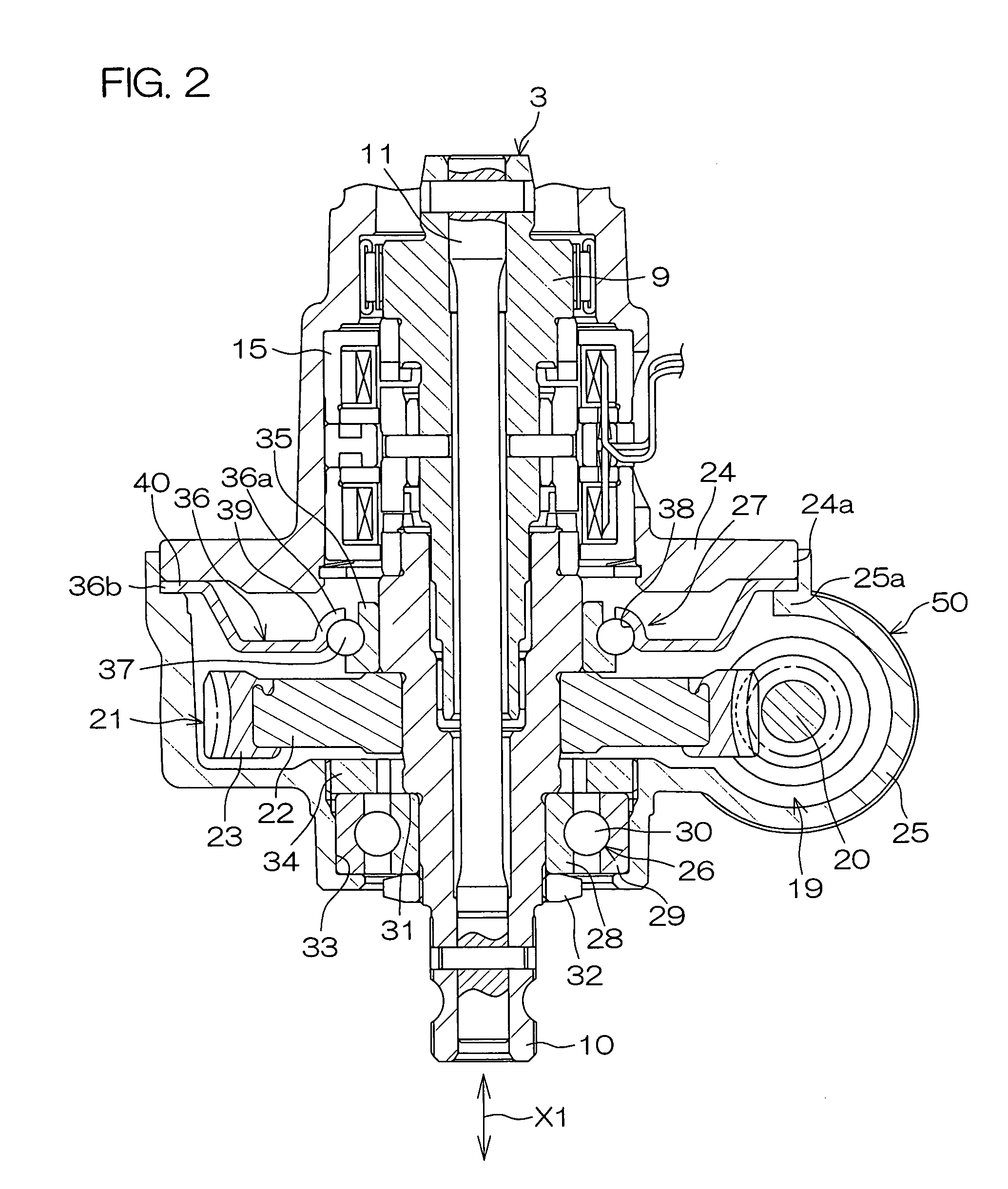
[0018]The steering shaft 3 comprises an input shaft 9 that continues to the steering member 2 and an output shaft 10 that continues to the pinion shaft 5. The input shaft 9 and the output shaft 10 are coupled so as to be relatively ro...


PUM


Abstract

An electric power steering apparatus comprises a transmission mechanism for transmitting driving force of a steering assisting electric motor to a steering mechanism. A driven gear of the transmission mechanism is rotatably supported by first and second bearings. One of the first and second bearings includes an inner ring coupled so as to be rotatable together with an output shaft of a steering shaft, an outer ring held on a housing, and a rolling element interposed between the inner ring and the outer ring. One of the inner ring and the outer ring includes an annular elastic plate giving a preload to the rolling element.

Description

BACKGROUND OF THE INVENTION[0001]1. Field of the Invention[0002]The present invention relates to an electric power steering apparatus that produces a steering assist force by an electric motor.[0003]2. Description of Related Arts[0004]A speed reduction mechanism is used in an electric power steering apparatus for a motor vehicle. Rotation of an output shaft of an electric motor is reduced in speed by, for example, a worm shaft and a worm wheel as the speed reduction mechanism. Thereby, output of the electric motor is amplified and is transmitted to a steering mechanism. As a result, a steering operation is assisted.[0005]The worm shaft and the worm wheel are accommodated in a housing. The worm wheel is together rotatably coupled to an output shaft of a steering shaft coupled to a steering member. The output shaft is rotatably supported by a pair of bearings arranged at both sides sandwiching the worm wheel in an axial direction of the output shaft. The pair of bearings is formed of,...

Claims


Application Information

Patent Timeline
IPC IPC(8): B62D5/04
CPCB62D5/0409F16C25/08F16C19/163F16C19/54F16C2361/61
Inventor IMAGAKI, SUSUMUSUNADA, SEIJINISHI, YOSHINORI
Owner JTEKT CORP
Why Eureka
Try Eureka