
Microphone device including light emitting elements

Active Publication Date: 2016-08-25
AUDIO-TECHNICA
View PDF4 Cites 0 Cited by
  • Summary
  • Abstract
  • Description
  • Claims
  • Application Information

AI Technical Summary

Benefits of technology

The invention is about a microphone device that includes light emitting elements. These elements can be controlled to turn on or off, and the device aims to prevent any unwanted noise caused by the LEDs being turned on or off. By controlling the lighting of multiple LEDs at the same time, the device can improve visibility. Furthermore, the device ensures a steady supply of power to the LEDs, even during switching between lighting and non-lighting, and also allows for a direct current to be supplied to the LEDs through constant current elements. Overall, this invention provides a microphone device that can effectively control the lighting of LEDs and prevent noise, while also ensuring sufficient power supply for the LEDs.

Problems solved by technology

However, a voltage value applied to the LED is decreased, and thus it becomes difficult to light a plurality of LEDs at the same time to enhance visibility of the LEDs.

Method used


Image

  • Microphone device including light emitting elements
  • Microphone device including light emitting elements
  • Microphone device including light emitting elements

Examples


Embodiment Construction

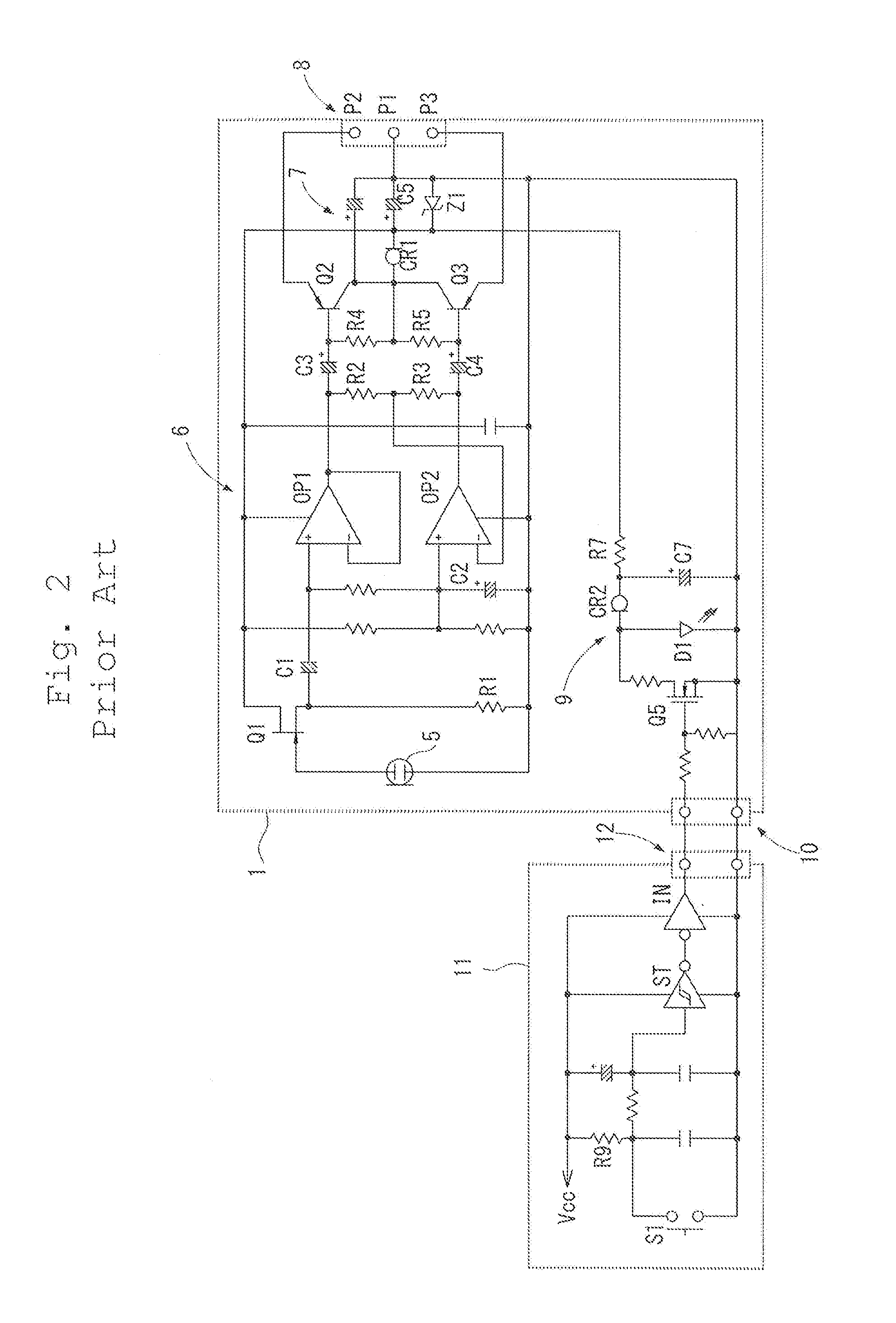
[0041]Hereinafter, a microphone device including light emitting elements according to the present invention will be described based on an embodiment illustrated in FIG. 3.

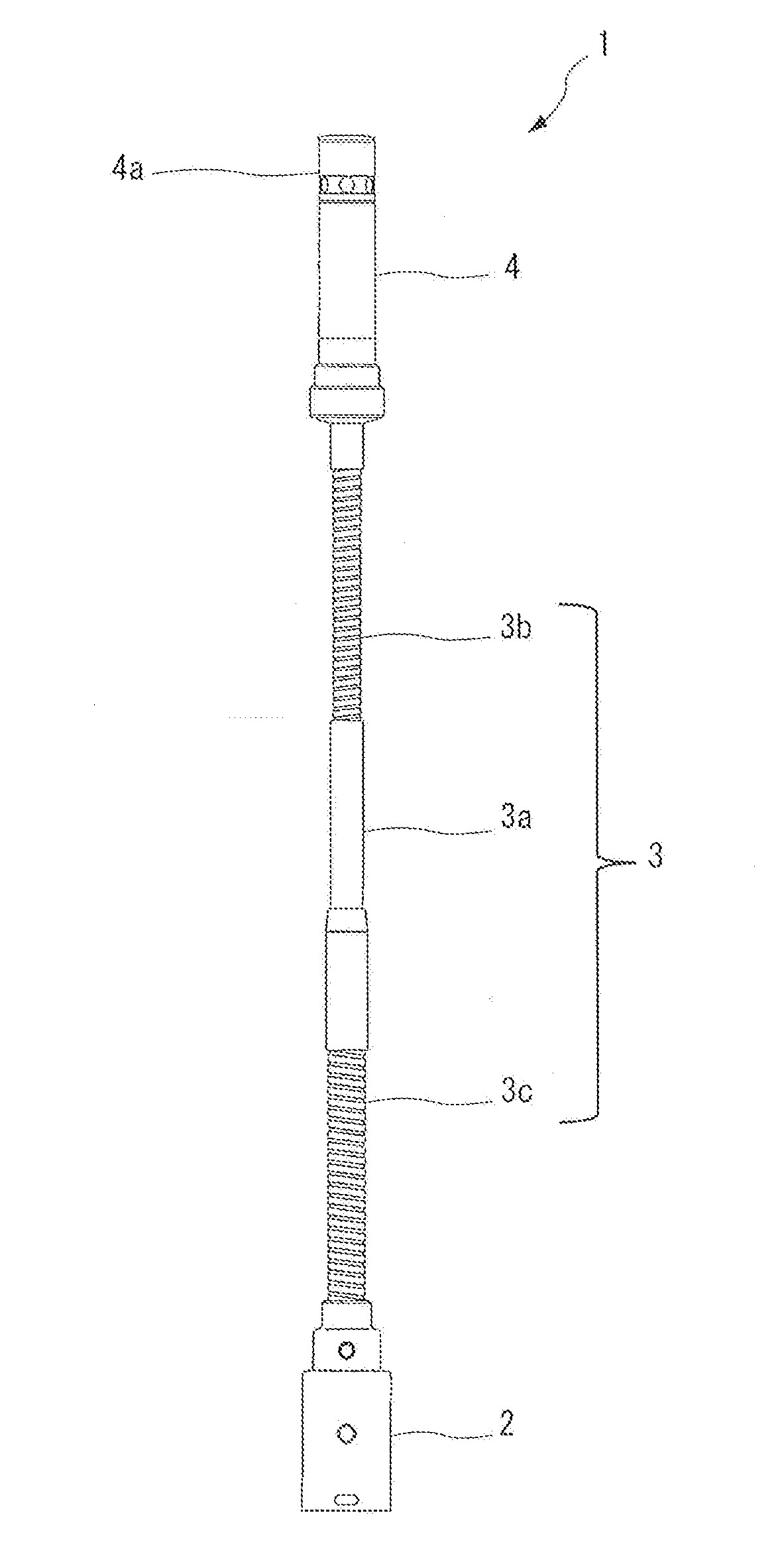
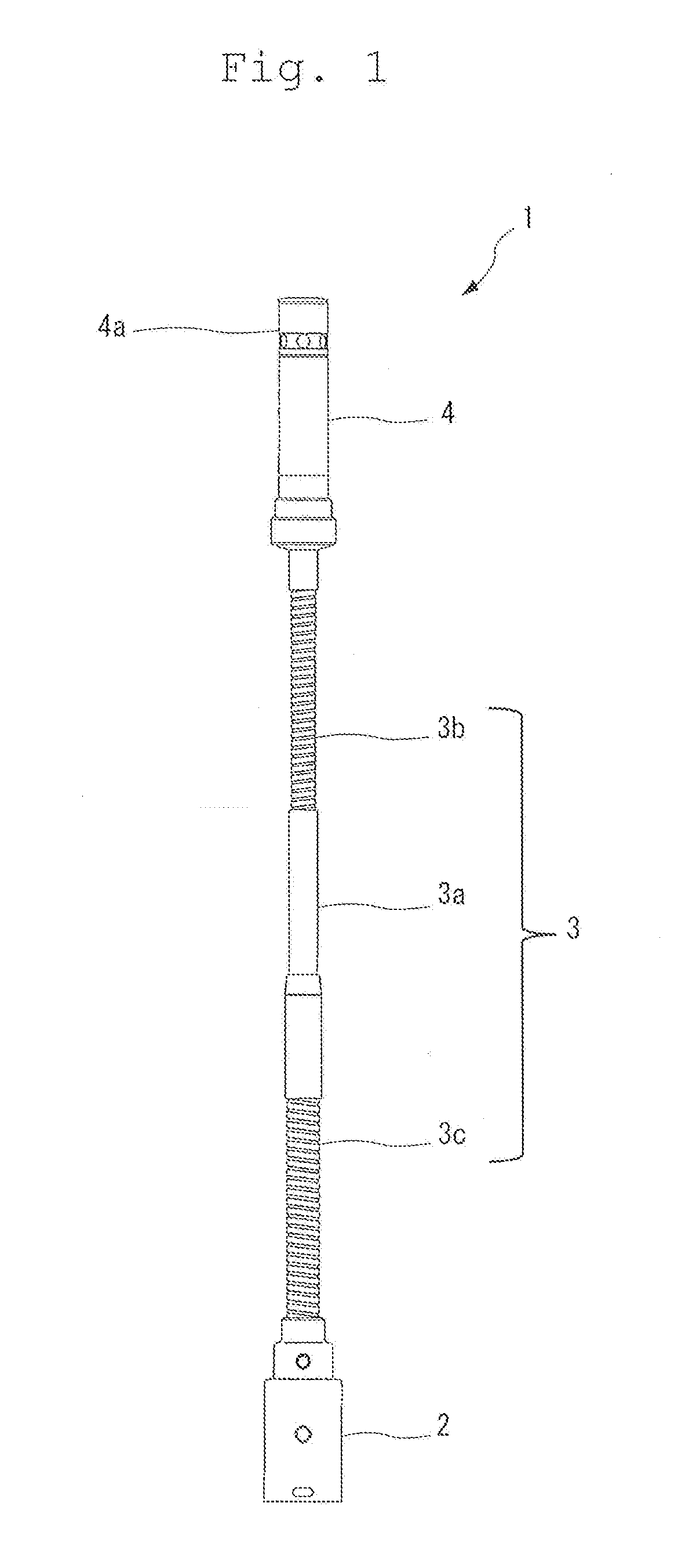
[0042]A microphone device 1 illustrated in FIG. 3 configures a gooseneck-type microphone, which is similar to the example illustrated in FIG. 1. A condenser microphone unit 5 mounted in a microphone case 4 configures an electret condenser microphone unit that includes an electret layer in either a diaphragm or a fixed electrode, which face each other.

[0043]Then, the one fixed electrode is connected to a gate of a field effect transistor (Q1) that functions as an impedance converter, and the other diaphragm is connected to a ground of the microphone device 1. Further, a direct current operation voltage is supplied from a power supply circuit 7 described below to a drain of the field effect transistor (Q1), and a source resistance R1 is connected to a source of the field effect transistor (Q1), so that the field effe...


PUM


Abstract

A microphone device includes an audio signal output circuit that balanced-outputs, through a balanced transmission line, an audio signal output from a condenser microphone unit, a balanced output terminal including a hot terminal, a cold terminal, and a ground terminal connected to the balanced transmission line, a power supply circuit that supplies a phantom power supply to the audio output circuit from the balanced output terminal through the balanced transmission line, and a display circuit including light emitting elements that perform lighting and non-lighting according to an operation of a manual switch, and the display circuit includes constant current elements that generate a constant current through the balanced transmission line, a constant voltage element connected to the constant current elements and which generates a constant voltage, and light emitting elements connected to the constant current elements, and to which the constant voltage by the constant voltage element is applied.

Description

BACKGROUND OF THE INVENTION[0001]1. Field of the Invention[0002]The present invention relates to a microphone device favorably used in conference rooms and the like, and especially relates to a microphone device including light emitting elements, which can suppress occurrence of noises based on switching of lighting and non-lighting of the light emitting elements included in the microphone.[0003]2. Description of the Related Art[0004]For example, as conference microphones installed on speech tables of conference rooms or tables of conference attendees, gooseneck-type microphones are provided. The gooseneck-type microphones include a stand arm with a long neck and including a flexible pipe that easily enables angle or height adjustment, and a microphone case in which a microphone unit is housed is attached to a tip portion of the stand arm.[0005]As the gooseneck-type microphones, typically, a small and light condenser microphone is used, and a phantom power feed system is employed in...

Claims


Application Information

Patent Timeline
IPC IPC(8): H04R1/02H04R1/32H04R19/04
CPCH04R1/028H04R1/326H04R19/04H04R19/016H04R27/00H04R2410/03H04M3/56
Inventor AKINO, HIROSHI
Owner AUDIO-TECHNICA
Learn More