Connector

a technology of connecting pins and connectors, applied in the direction of coupling device connection, securing/insulating coupling contact members, electrical devices, etc., can solve the problems of error absorbing, error in connection position of terminals with mating sides, etc., to improve durability, retain reliably, and improve the effect of durability

Inactive Publication Date: 2009-04-16
SUMITOMO WIRING SYST LTD
View PDF2 Cites 34 Cited by
  • Summary
  • Abstract
  • Description
  • Claims
  • Application Information

AI Technical Summary

Benefits of technology

[0010]An error in a connected position of the terminal with a mating side may exist. However, such an error is absorbed by a displacement of the terminal in the cavity. Accordingly, the terminal will not be pressed against the resin locking lance or the surrounding wall of the cavity to absorb the error. As a result, durability is improved. Further, the terminal is retained reliably by the locking lance even if the terminal is displaced in the cavity.
[0011]The locking lance preferably is at an upper wall of the cavity above the terminal. Thus, the weight of the terminal will not act on the resin locking lance and durability is improved further.
[0015]The reinforcing walls may extend parallel to panels of the surrounding wall from corners of the surrounding wall. In this way, a force receiving direction of the surrounding wall from the reinforcing wall coincides with the direction of the surrounding wall. Bending rigidity in the direction of the surfaces of the panels of the surrounding wall is drastically higher than bending rigidity in the thickness direction. Thus, a force from the reinforcing wall will not deform the surrounding wall.

Problems solved by technology

An error in a connected position of the terminal with a mating side may exist.
However, such an error is absorbed by a displacement of the terminal in the cavity.

Method used


Image

  • Connector
  • Connector
  • Connector

Examples


Embodiment Construction

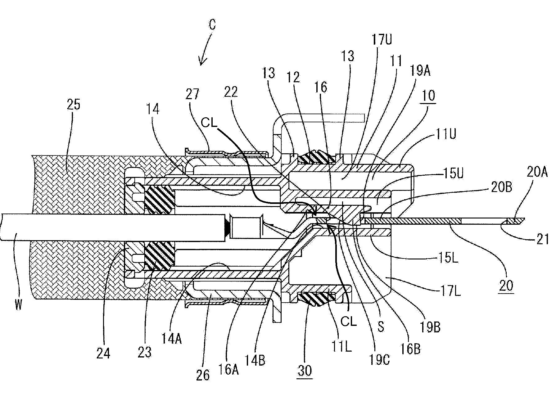
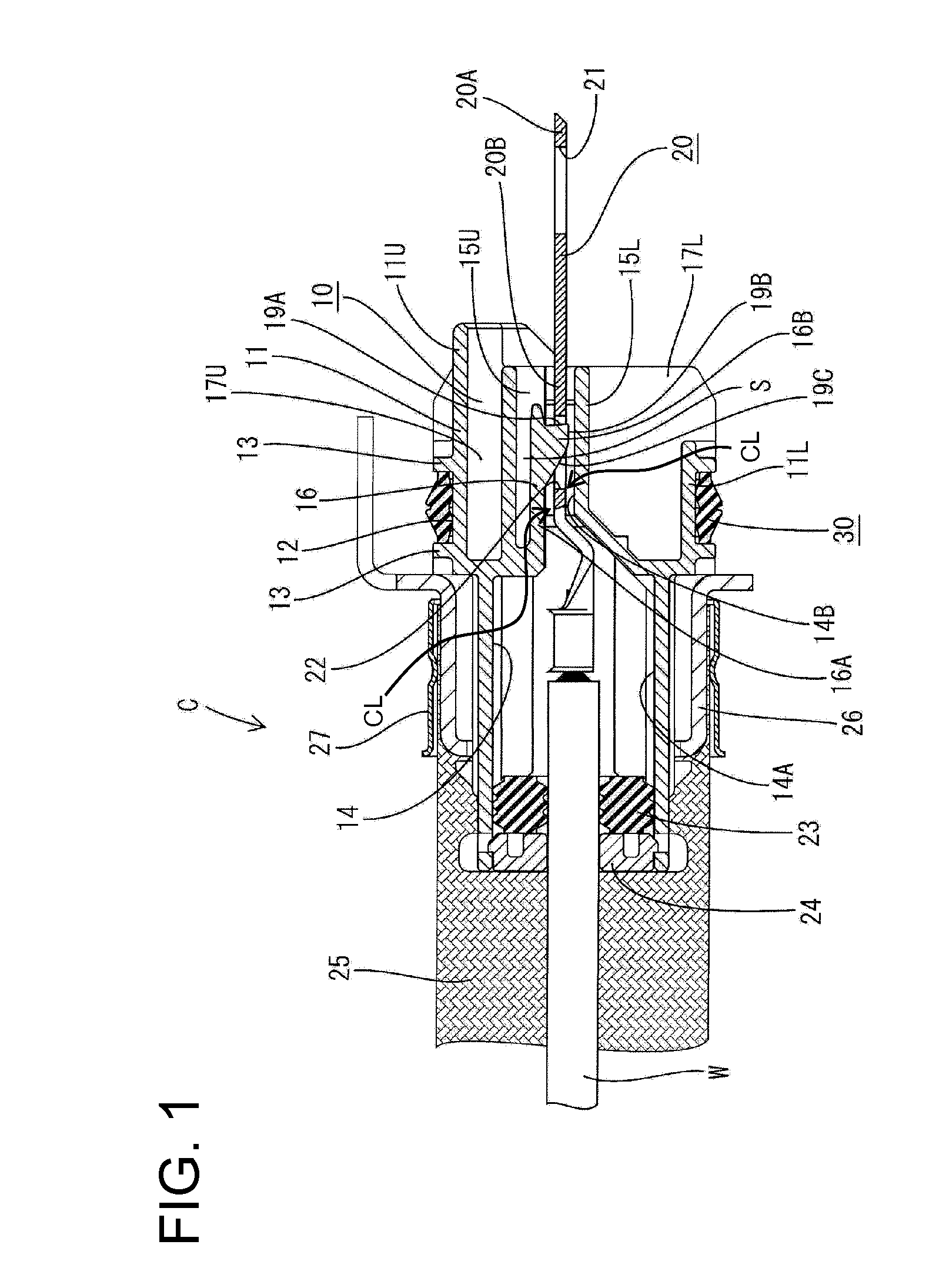
[0029]A connector in accordance with the invention is identified by the letter C in FIGS. 1 to 9. The connector C is to be fit in a mounting hole 41 of a shielding case 40 of an unillustrated device (e.g. an inverter, motor or the like of an electric vehicle).

[0030]The connector C includes a housing 10 made e.g. of synthetic resin. A front portion of the housing 10 is to be fit in the mounting hole 41 of the shielding case 40 and a rear portion thereof projects out from the shielding case 40 (see FIG. 9).

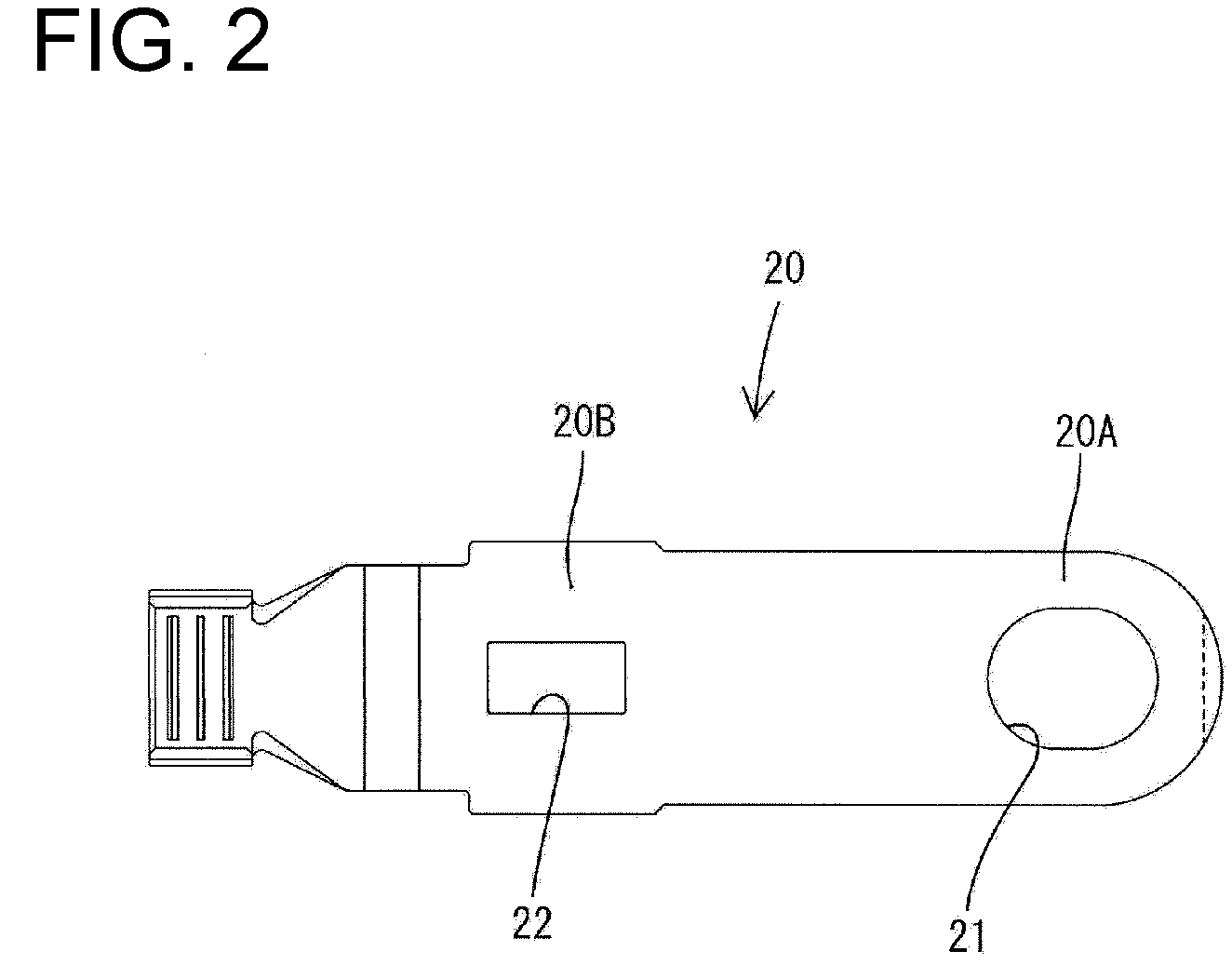
[0031]Each terminal 20 accommodated in the housing 10 is long in forward and backward directions. A connecting portion 20A is formed at the front end of each terminal 20 and is formed with a bolt hole 21. The connecting portion 20A is placed on an upper surface a terminal mount T and is secured by a bolt.

[0032]An engageable portion 20B is formed at the rear end of the terminal 20 and is formed with an engaging hole 22. As shown in FIG. 2, the engaging hole 22 is a substantially rect...


PUM


Abstract

A housing (10) made of synthetic resin, in which plate-like terminals (20) are to be accommodated, is formed with cavities (14), into which the terminals (20) are inserted, and resin locking lances (16) extending along surrounding walls (15) of the cavities (14). An engaging projection (16B) engageable with an engaging hole (22) of the terminal (20) projects from the resin locking lance (16). A clearance CL for permitting displacements of the terminal (20) is defined between a facing wall (15L) of the surrounding wall (15) of the cavity (14) facing the resin locking lance (16) and a main body (16A) of the resin locking lance (16) excluding the engaging projection (16B). A projecting distance of the engaging projection (16B) is longer than a difference between the dimension of the clearance and the thickness of the terminal (20).

Description

BACKGROUND OF THE INVENTION[0001]1. Field of the Invention[0002]The invention relates to a connector, in which a plate-like terminal is retained by a resin locking lance.[0003]2. Description of the Related Art[0004]U.S. Pat. No. 7,101,217 discloses a connector that has a housing formed with cavities and resin locking lances adjacent the cavities. Each lock lance has a main body and an engaging projection that projects from the main body. Plate-like terminals are inserted into cavities. Each terminal is formed with an engaging hole that receives the engaging projection of the respective locking lance to hold the terminal in the cavity. Parts of the terminal near the engaging hole are squeezed between a wall of the cavity and the main body of the resin locking lance. A front end portion of the terminal before the engaging hole projects forward from the housing and is bolted on an upper surface of a terminal mount.[0005]The upper surface of the terminal mount and the front end portions...

Claims


Application Information

Patent Timeline
Patent Type & Authority Applications(United States)
IPC IPC(8): H01R13/40
CPCH01R9/032H01R13/5221H01R13/4223H01R11/12H01R13/65912
Inventor KAWAMURA, MASAYUKI
Owner SUMITOMO WIRING SYST LTD
Why Eureka
Try Eureka