User specific climate control system

a climate control system and user-specific technology, applied in ventilation systems, heating types, valve parts, etc., can solve the problems of unsafe driving conditions, inability to safely operate, and unsafe driving conditions for vehicles employing vent units

Inactive Publication Date: 2009-04-16
FAURECIA INTERIOR SYST
View PDF15 Cites 20 Cited by
  • Summary
  • Abstract
  • Description
  • Claims
  • Application Information

AI Technical Summary

Benefits of technology

[0006]In accordance with the present invention, a climate control system is provided with a master vent control unit that the driver may adjust for the desire direction of airflow. After he does so, a control system adjusts the position of the remaining vents so as to direct air flow to substantially the same location in the vehicle. Preferably, a similar control vent is provided on the passenger side of the vehicle. Should a passenger adjust that vent, the control system will adjust the remaining vents on his side to direct the air flow to the same position in the passenger vehicle that he has selected. Preferably, the seat sensor, or the like, is provided which causes the passenger vents to be readjusted to the driver's selection when he is no longer present. Alternatively, the passenger control vent unit may simply have a sensor that overrides the driver's adjustment for the passenger vents when operated, and that adjustment is retained until the vehicle is turned off and / or re-started.

Problems solved by technology

Since some of them are normally out of his reach, he is not able to do so in a safe manner while driving, without taking his attention from the road and risking an accident.
Because the driver must make complex body and / or arm movements when manually adjusting and positioning each of the air flow vents out of his reach, vehicles employing such vent units lack desired ergonomics and ease of operation for controlling climate and / or air flow in the vehicle while contributing to unsafe driving conditions.

Method used


Image

  • User specific climate control system
  • User specific climate control system
  • User specific climate control system

Examples


Embodiment Construction

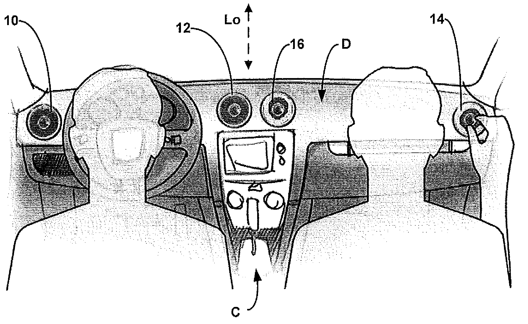
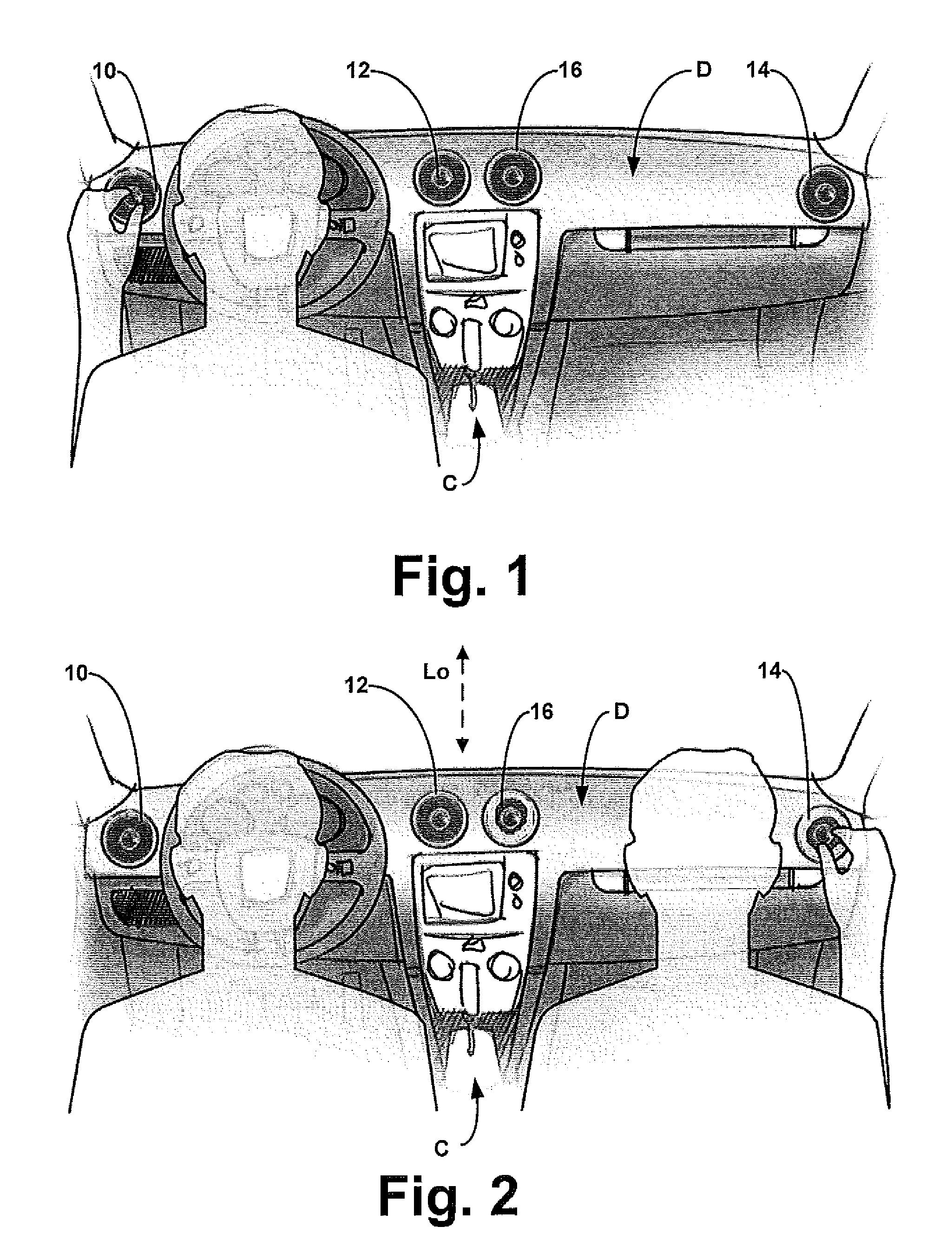
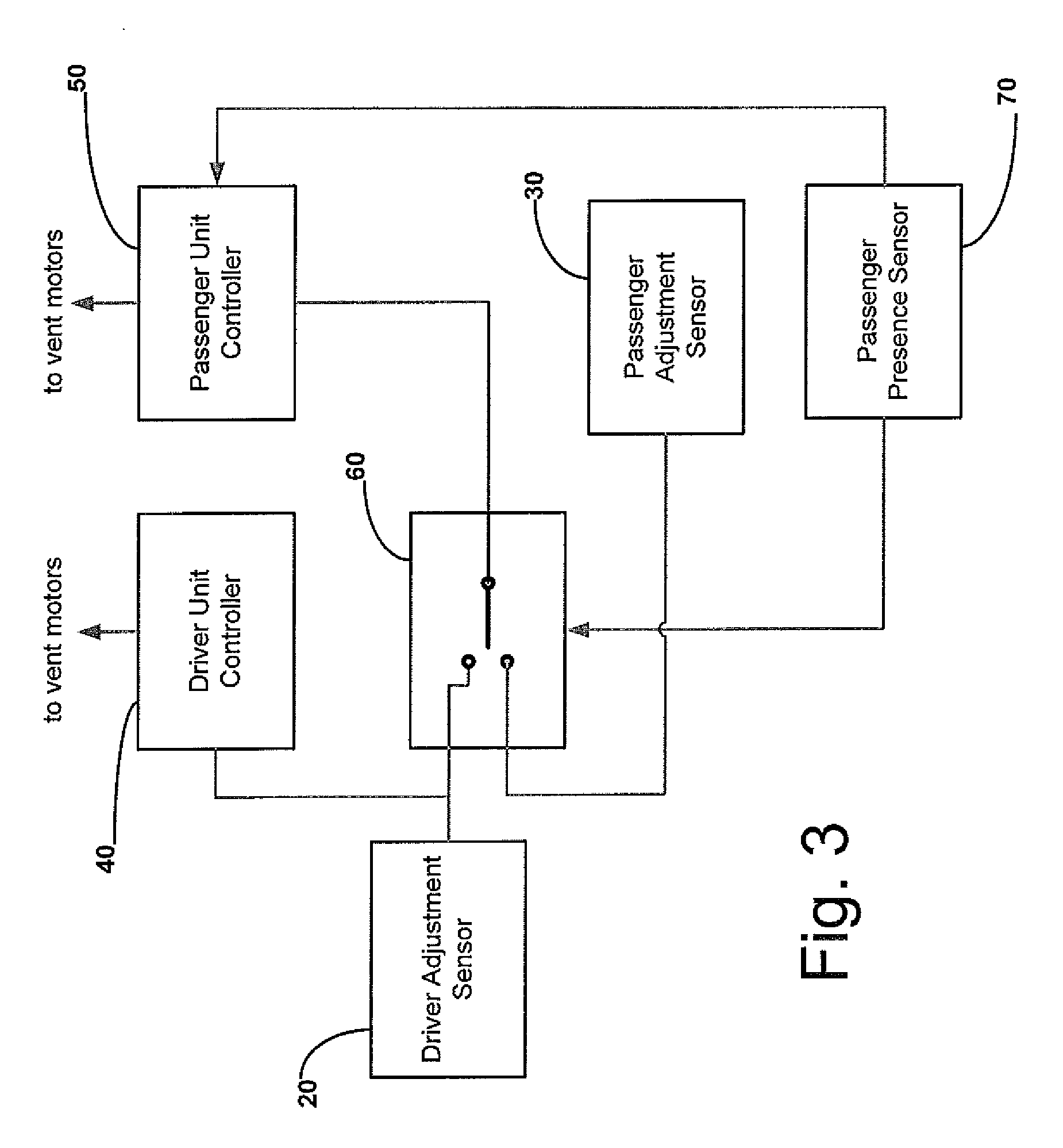
[0028]Vehicle climate control systems are disclosed herein for controlling airflow direction with the use of control units for adjusting and positioning one or more airflow direction devices for one or more users, such as a driver, a passenger, etc. The systems may be employed in automobiles, planes, trains, trucks, buses, boats, helicopters, submersible vehicles, spacecraft, or the like. In particular, the present invention relates to vehicle climate control systems that provide desired ergonomics and ease of operation (e.g., due to less complex arm movement without having to manually adjust and position each airflow direction device separately) of at least one control unit that adjusts and positions airflow direction devices to provide desired airflow according to the desired adjustments of the one or more users.

[0029]Turning now to the details of the drawings, FIG. 1 is an interior view of an automobile showing a driver from the rear and a dashboard D in accordance with at least ...


PUM


Abstract

A climate control system is provided with a control vent unit that a driver may adjust for a desired direction of airflow. After the driver does so, a control system automatically and/or simultaneously adjusts the position of the remaining vents so as to direct respective air flow to substantially the same location in the vehicle. Preferably, a similar control vent is provided on the passenger side of the vehicle. Should a passenger adjust the passenger control vent unit, the control system will automatically and/or simultaneously adjust the remaining vents on the passenger side to direct the respective air flow to the selected position in the passenger side of the vehicle.

Description

CROSS-REFERENCE TO RELATED APPLICATIONS[0001]This application claims the benefit of U.S. Provisional Patent Application No. 60 / 978,876, filed Oct. 10, 2007, the entirety of which is incorporated herein by reference.FIELD OF THE INVENTION[0002]The present invention is directed to climate control systems that employ control units to adjust and position one or more airflow direction devices for one or more users, for use in a vehicle, or the like.BACKGROUND OF THE INVENTION[0003]The present invention relates generally to climate control systems of the type used in automotive vehicles and, more particularly, concerns an improvement to climate control systems which allows them to be adjusted to the preference of the driver and the passengers simultaneously and / or automatically.[0004]Climate control systems are now available in virtually all new vehicles. Some such systems allow individualized control by the driver and the passenger, even when they are both sitting side-by-side, for examp...

Claims


Application Information

Patent Timeline
Patent Type & Authority Applications(United States)
IPC IPC(8): B60H1/34F24F7/007B60H1/00G05D7/00
CPCB60H1/00742F24F2011/0035F24F11/0034B60H1/00871F24F11/30F24F2120/10F24F2120/12
Inventor HOTARY, JAMES
Owner FAURECIA INTERIOR SYST
Why Eureka
Try Eureka