Debug instruction for use in a data processing system

a data processing system and instruction technology, applied in the field of data processing systems, can solve problems such as less predictable execution and especially problematic in real-time applications

Active Publication Date: 2009-04-16
RAMBUS INC
View PDF9 Cites 9 Cited by
  • Summary
  • Abstract
  • Description
  • Claims
  • Application Information

AI Technical Summary

Problems solved by technology

However, removal of these debug instructions can change the execution characteristics of the system which may result in less predictable execution.
This may be especially problematic in real-time applications.

Method used


Image

  • Debug instruction for use in a data processing system
  • Debug instruction for use in a data processing system
  • Debug instruction for use in a data processing system

Examples


Embodiment Construction

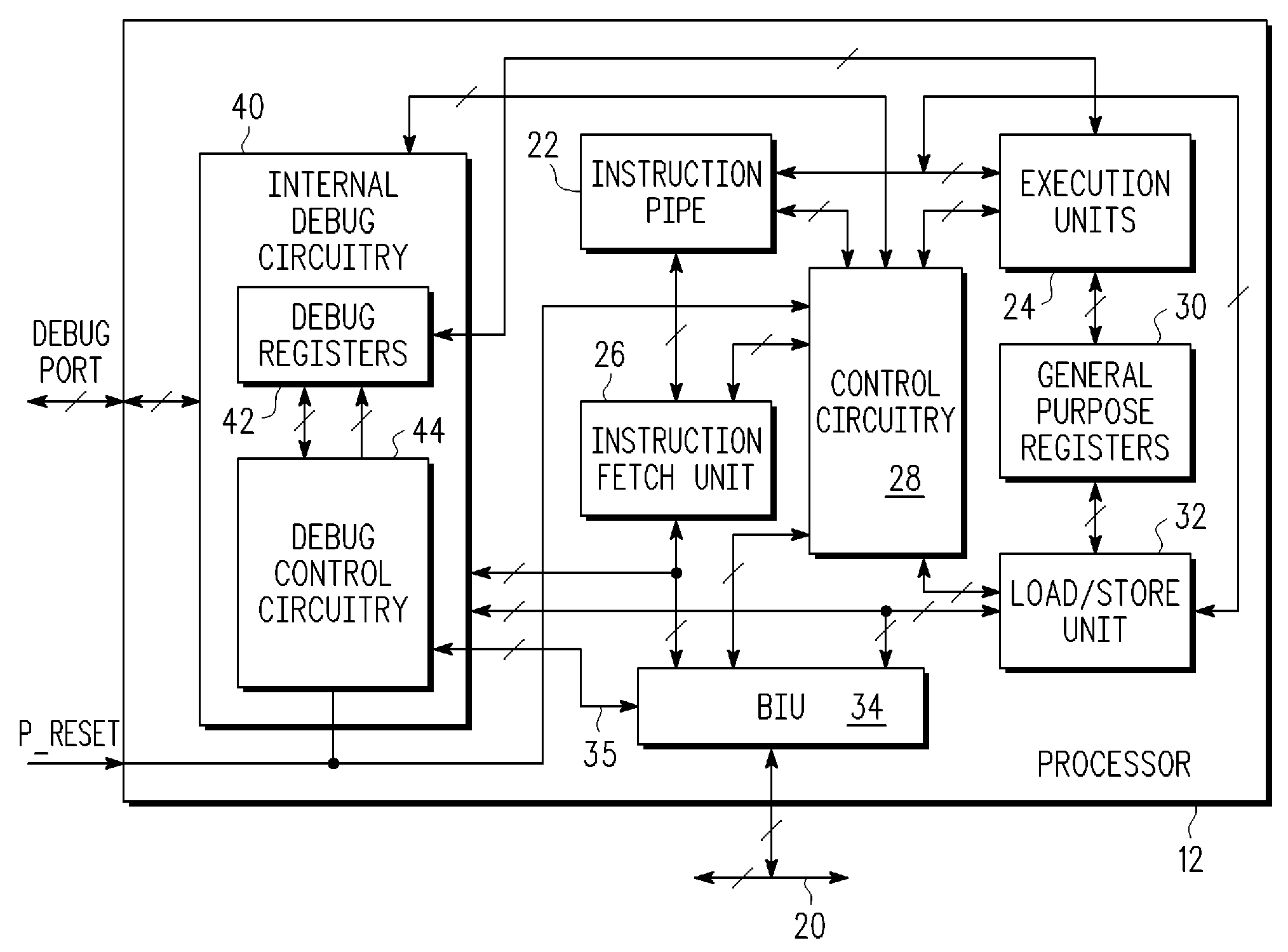
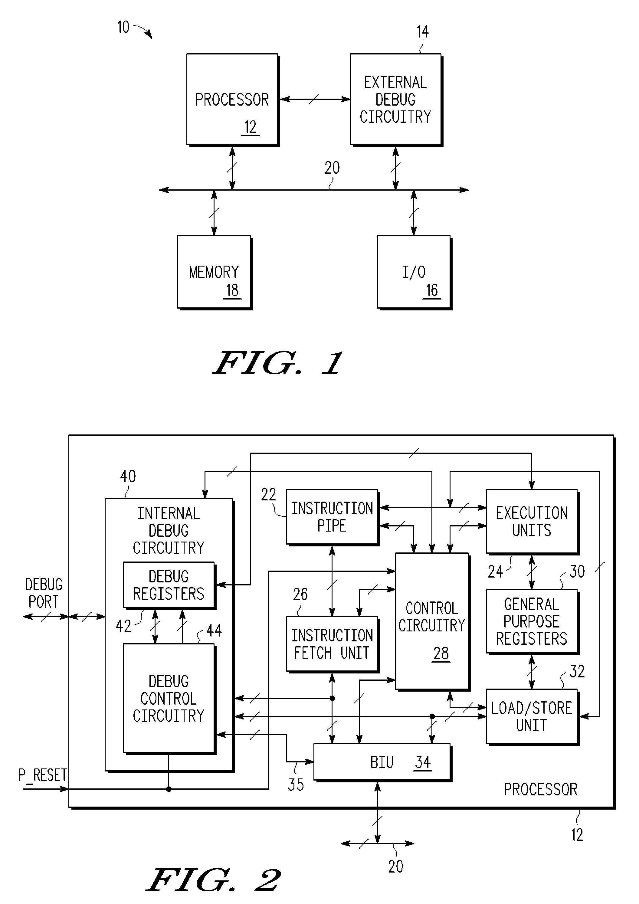
[0017]Current debug instructions provide the capability of conditionally entering a debug halted mode (i.e. a debug mode) or else causing a software debug exception (i.e. a debug interrupt) under software control during the software development process, to allow software or hardware debug operations to take place. However, once software development is complete, those debug instructions which remain embedded in the finalized code will result in undesired exceptions and thus must be removed. However, removal of these debug instructions changes the execution characteristics of the system. That is, the code image itself changes since branch targets, page boundaries, and other instruction relationships may change upon removal of the debug instructions. In order to allow the code image itself to remain unchanged and thus possibly provide for more predictable execution, one embodiment discussed herein provides additional control to allow debug instructions to operate as “no-op” instruction...


PUM


Abstract

A method includes providing a debug instruction and providing a debug control register field, where if the debug control register field has a first value, the debug instruction executes a debug operation and where if the debug control register field has a second value, the debug instruction is to be executed as a no-operation (NOP) instruction. A data processing system includes instruction fetch circuitry for receiving a debug instruction, a debug control register field, and debug execution control circuitry for controlling execution of the debug instruction in a first manner if the debug control register field has a first value and in a second manner if the debug control register field has a second value, where in the first manner a debug operation is performed and in the second manner no debug operation is performed.

Description

BACKGROUND[0001]1. Field[0002]This disclosure relates generally to data processing systems, and more specifically, to a debug instruction for use in a data processing system.[0003]2. Related Art[0004]Debug instructions are commonly used during software development to allow debug operations to take place. Once the software has been developed and checked with debug instructions, these debug instructions are removed so as not to cause undesired exceptions in the software application. However, removal of these debug instructions can change the execution characteristics of the system which may result in less predictable execution. This may be especially problematic in real-time applications.BRIEF DESCRIPTION OF THE DRAWINGS[0005]The present invention is illustrated by way of example and is not limited by the accompanying figures, in which like references indicate similar elements. Elements in the figures are illustrated for simplicity and clarity and have not necessarily been drawn to sc...

Claims


Application Information

Patent Timeline
Patent Type & Authority Applications(United States)
IPC IPC(8): G06F9/44
CPCG06F9/3005G06F11/3656G06F9/30181G06F9/30072
Inventor MOYER, WILLIAM C.SNYDER, MICHAEL D.WHISENHUNT, GARY L.
Owner RAMBUS INC
Why Eureka
Try Eureka