
Media, filter element using corrugated media sheet, corrugated sheet, and methods

a filter element and media sheet technology, applied in the field of filter elements, corrugated webs, corrugated webs, etc., can solve problems such as substantial damage to equipmen

Inactive Publication Date: 2009-04-23
DONALDSON CO INC
View PDF62 Cites 36 Cited by
  • Summary
  • Abstract
  • Description
  • Claims
  • Application Information

AI Technical Summary

Problems solved by technology

If the particulate material reaches the internal workings of the various mechanisms involved, it can cause substantial damage to the equipment.

Method used


Image

  • Media, filter element using corrugated media sheet, corrugated sheet, and methods
  • Media, filter element using corrugated media sheet, corrugated sheet, and methods
  • Media, filter element using corrugated media sheet, corrugated sheet, and methods

Examples


Embodiment Construction

I. Some Principles Related to Filter Design

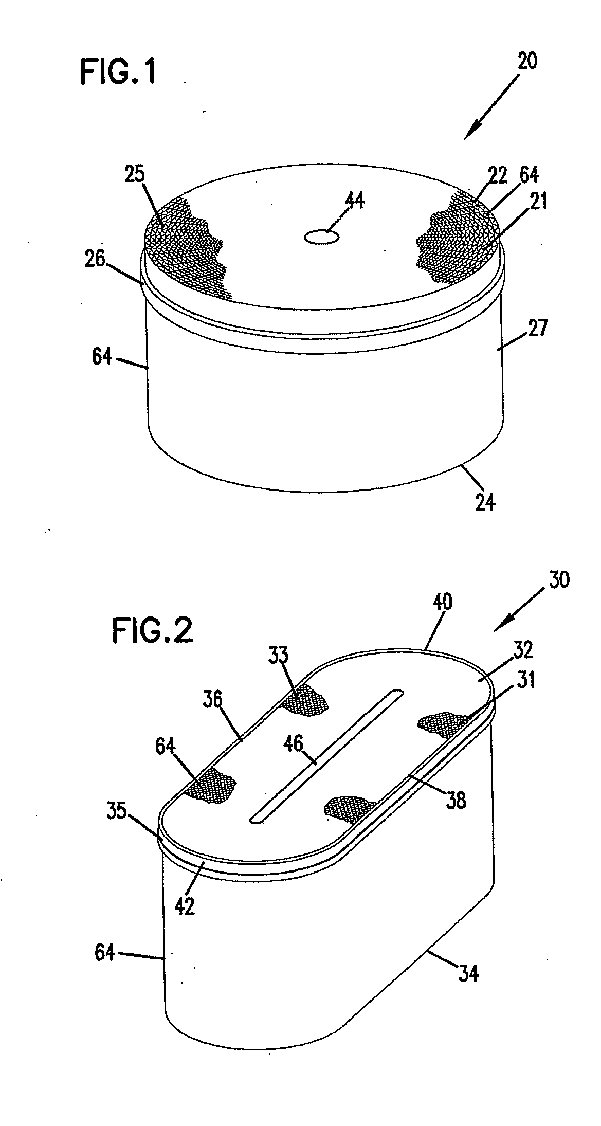
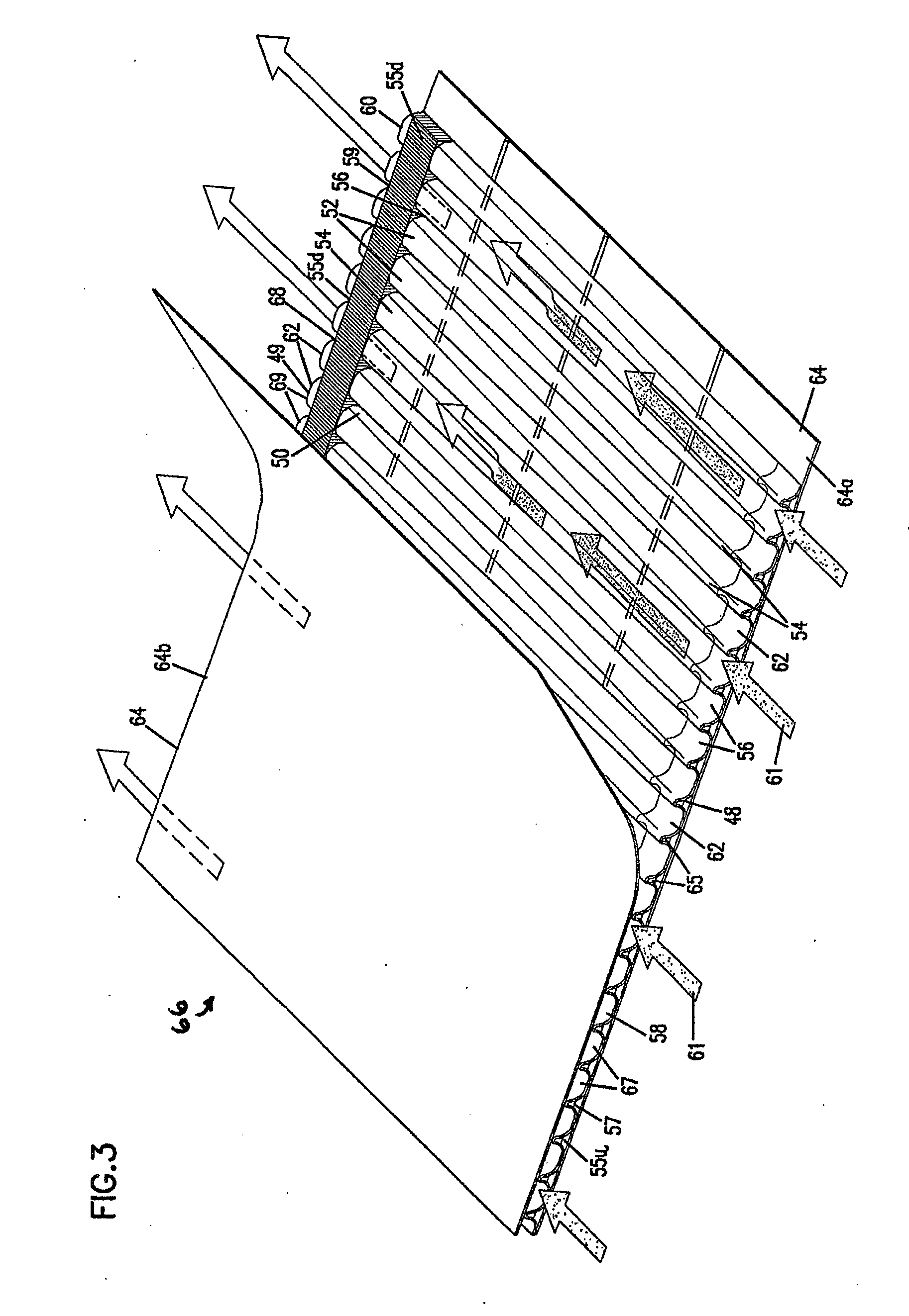
[0025]Filter elements utilizing fluted filter media, which accommodate straight through flow are known. Examples of some these type of filter elements are shown in U.S. Pat. Nos. 6,190,432; 5,820,646; and PCT Publication WO 97 / 40918, published on Nov. 6, 1997. Each of these patents and publication is incorporated by reference herein. In these types of filter elements, a corrugated sheet or web of filter media is attached to a flat sheet or web of material to result in a corrugated substrate. In many instances, the corrugated substrate is coiled or wound into a desired resulting element shape. Each individual corrugation, or flute, has one end open and the opposite end closed. Fluid to be filtered passes into open ends of selected ones of the flutes in the filter element. The fluid cannot proceed directly to exit out of the particular flute that it entered, because that particular flute is closed at the downstream end. In order to exit the d...


PUM

PropertyMeasurementUnit
radiusaaaaaaaaaa
radiusaaaaaaaaaa
radiusaaaaaaaaaa

Abstract

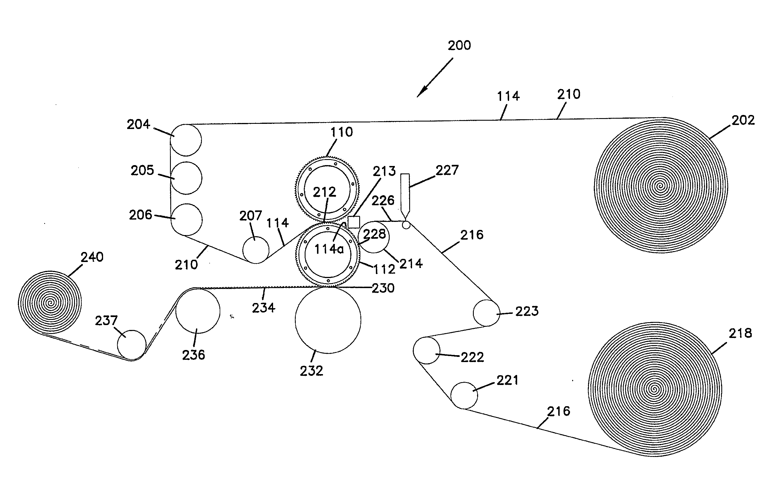
A corrugated web having tapered flutes is usable in straight-through flow filter elements. The corrugated web can be made by passage between a pair of corrugated rollers having tapered teeth. Methods of making usable corrugated rollers include methods for generating the tapered teeth at the end points and the extension between the end points. Corrugated webs may be made from a variety of media, including certain media that stretches in the machine direction. Methods of forming the corrugated web into filter elements (e.g., air filter elements) includes forming filter media by securing a flat sheet to the corrugated web. The filter media may then be wound into a filter element, including application of sealant during the winding process to close selected flutes.

Description

TECHNICAL FIELD[0001]This disclosure relates in general to corrugated webs, methods of making corrugated webs, and filter elements. In particular, this disclosure relates to corrugated webs having tapered flutes, methods and equipment for making such corrugated webs, methods of constructing filter elements (e.g., air filter elements) from such corrugated webs, and the resulting filter elements.BACKGROUND[0002]Air streams often carry particulate material therein. In many instances, it is desirable to remove some or all of the particulate material from an air stream. For example, air flow stream to engines for motorized vehicles or to power generation equipment; gas streams directed to gas turbine systems; and air streams to various combustion furnaces, often include particulate material therein. Also, liquid streams into engine lube systems or hydraulic systems also carry particulate matter within it. If the particulate material reaches the internal workings of the various mechanisms...

Claims


Application Information

Patent Timeline
Patent Type & Authority Applications(United States)
IPC IPC(8): B29C59/04B01D39/16B01D39/00B01D39/18B01D46/00B01D46/10B01D46/52H01P1/18H01Q3/30
CPCB01D39/1623B01D39/18B01D2275/208B01D46/10B01D46/527B01D46/0001
Inventor GOLDEN, PATRICKMADDEN, MICHAEL A.
Owner DONALDSON CO INC
Learn More