Decoding apparatus, image processing apparatus, recording medium, and decoding method

a decoding apparatus and image processing technology, applied in the direction of digital output to print units, instruments, digital computers, etc., can solve the problem of increasing production costs

Inactive Publication Date: 2009-04-23
FUJIFILM BUSINESS INNOVATION CORP
View PDF26 Cites 3 Cited by
  • Summary
  • Abstract
  • Description
  • Claims
  • Application Information

AI Technical Summary

Benefits of technology

[0008]According to an aspect of the invention, there is provided a decoding apparatus including an acquiring unit that divides one line of image data in a main scan direction into blocks for every n consecutive pixels (n is a positive integer not smaller than two) to acquire compressed pixel data generated by compressing each of the divided blocks; a decompressing unit that decompresses the acquired compressed pixel data on the basis of the blocks; first and second data retaining units that retain the decompressed one-line pixel data; a first switching unit that alternately switches the first or second data retaining unit defined as a write destination of the pixel data decompressed by the decompressing unit; a second switching unit that alternately switches the first or second data retaining unit defined as a readout source of pixel data such that the pixel data are read out from the first or second data retaining unit not defined as the write destination of the pixel data by the first switching

Problems solved by technology

However, to implement the image edit process such as the mirror image printing in the convention case, the line buffer for the image

Method used


Image

  • Decoding apparatus, image processing apparatus, recording medium, and decoding method
  • Decoding apparatus, image processing apparatus, recording medium, and decoding method
  • Decoding apparatus, image processing apparatus, recording medium, and decoding method

Examples


first exemplary embodiment

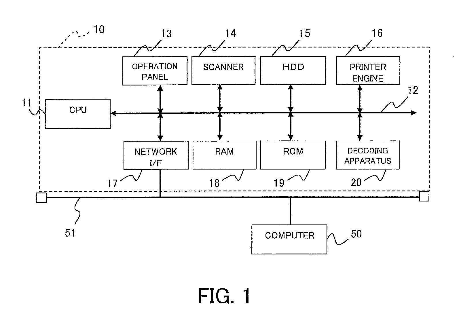
[0019]FIG. 1 depicts an example of a hardware configuration of an image processing apparatus 10 according to the present invention. The image processing apparatus 10 of this exemplary embodiment is a multi-function device equipped with a print function and a copy function that implement various functions such as the mirror image printing and the shift printing and is an apparatus with a built-in computer. In FIG. 1, a CPU 11 controls operations of various mechanisms mounted on the apparatus, such as a scanner 14 and a printer engine 16, in accordance with a program stored in a ROM 19. An address data bus 12 is connected to various mechanisms to be controlled by the CPU 11 for data communication. An operation panel 13 accepts instructions from users such as instructions for the mirror image printing and the shift printing and displays information. A scanner 14 scans a manuscript set by user and stores it as electronic data in storage such as an HDD (hard disk drive) 15. The HDD 15 st...

second exemplary embodiment

[0038]FIG. 5 is a configuration view of the line buffer 26 of this exemplary embodiment. Although the line buffer 26 is implemented with a three-port memory in the first exemplary embodiment, the line buffer 26 is implemented with a two-port memory, which is inexpensive, in this exemplary embodiment.

[0039]The readout control signal 34 output from the switching portion 25 is always sent out to the line buffer 26 different from the line buffer 26 to which the write control signal 32 sent out. That is, since the writing operation and the readout operation of the pixel data are exclusive to each other, the operation same as the first exemplary embodiment may be performed by providing one read / write pointer managing unit 44 as in this exemplary embodiment without separately providing the read pointer managing unit 41 and the write pointer managing unit 42 as is the case with the first exemplary embodiment. That is, the read / write pointer managing unit 44 initializes the pointer indicatin...

third exemplary embodiment

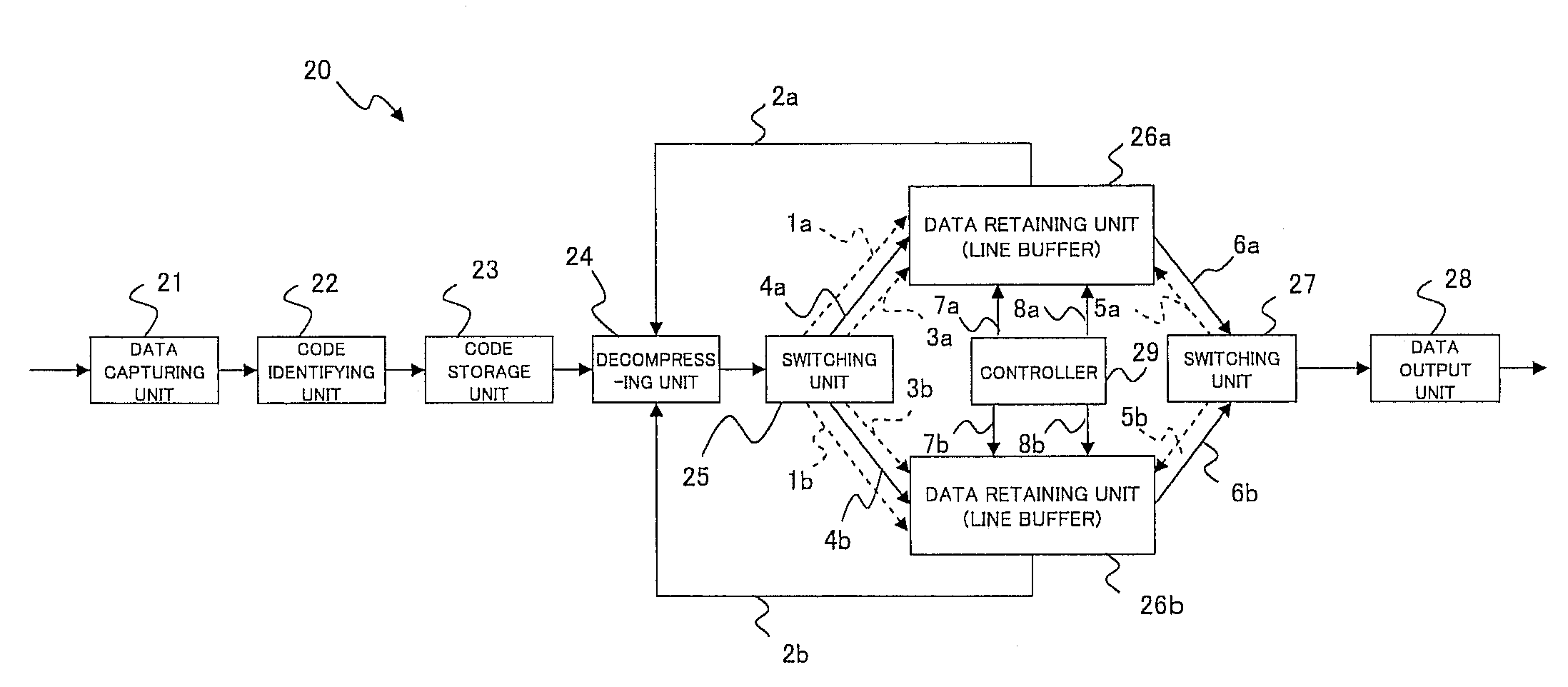
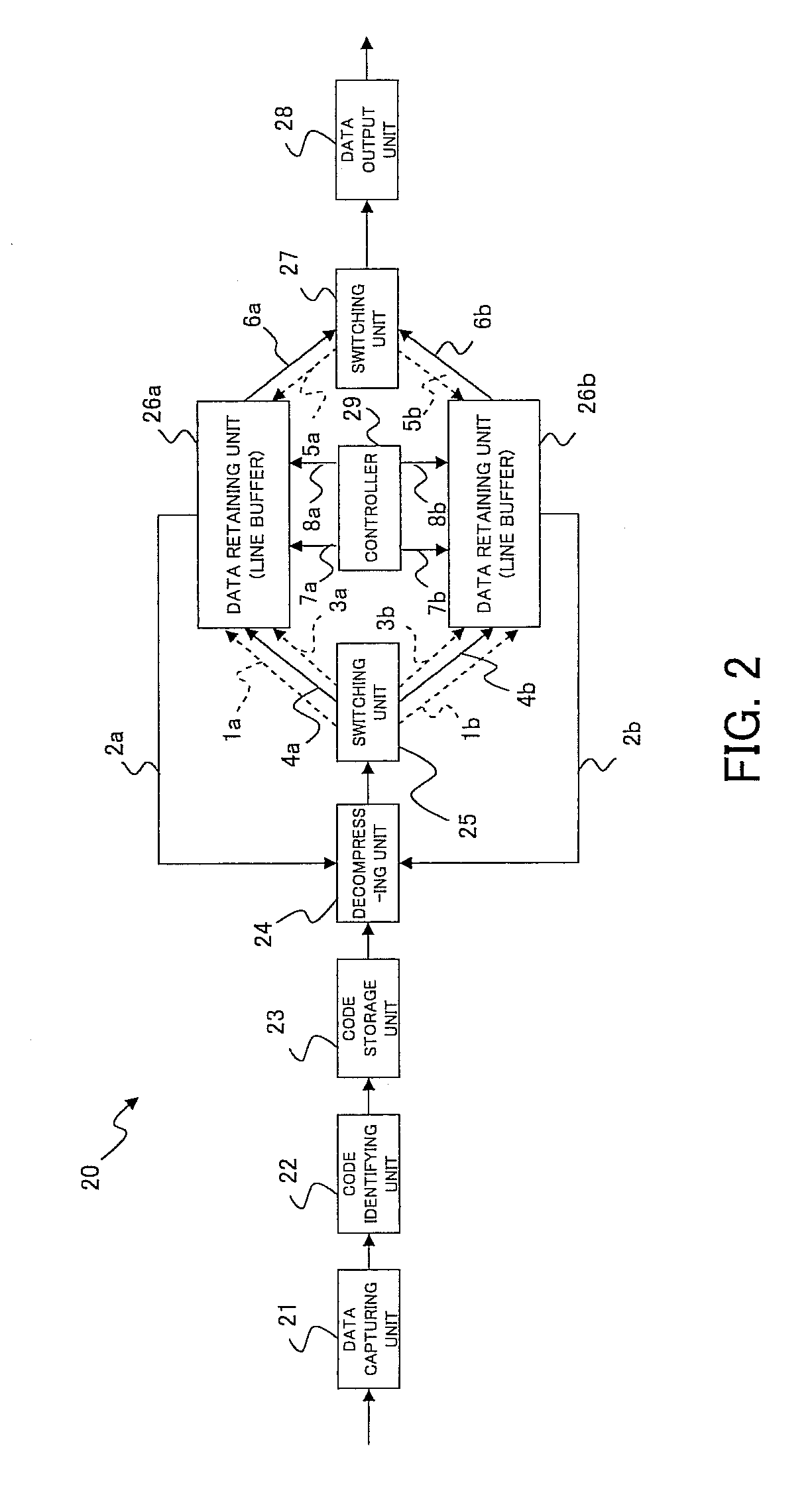
[0042]FIG. 6 is a block configuration view of the decoding apparatus 20 of this exemplary embodiment. The decoding apparatus 20 of this exemplary embodiment has a configuration of the first exemplary embodiment with a switching unit 52 and a data retaining unit 53 added. The data retaining unit 53 may have the configuration same as the data retaining unit 26 and is made up of a line buffer retaining one line of decompressed pixel data. The switching unit 52 alternately switches the data retaining units 26a and 26b retaining the pixel data to be output as is the case with the switching unit 27. The data retaining unit 26 retains the last decompressed pixel data, and the data retaining unit 53 retains the pixel data retained by the data retaining unit 26. That is, the data retaining unit 26 retains the pixel data decompressed one step before while the data retaining unit 53 retains the pixel data decompressed two steps before.

[0043]FIG. 7 is a conceptual view of blocks stored in the d...


PUM


Abstract

An acquiring unit divides one line of image data in a main scan direction into blocks for every n consecutive pixels to acquire compressed pixel data generated by compressing each of the divided blocks. A first switching unit alternately switches a first or second data retaining unit defined as a write destination of the decompressed pixel data. A second switching unit alternately switches the first or second data retaining unit defined as a readout source of pixel data such that the pixel data are read out from the first or second data retaining unit not defined as the write destination of the pixel data by the first switching unit. A controller controls output of the pixel data from the first or second data retaining unit.

Description

CROSS-REFERENCE TO RELATED APPLICATIONS[0001]This application is based on and claims priority under 35 USC 119 from Japanese Patent Application, No. 2007-274758 filed on Oct. 23, 2007.BACKGROUND[0002]1. Technical Field[0003]The present invention relates to a decoding apparatus, an image processing apparatus, a recording medium, and a decoding method.[0004]2. Related Art[0005]When a computer user transmits print data to a printer for printing, a computer often transmits print data after compressing the data in accordance with a predetermined compression mode to reduce a data transmission amount. However, the printer performs a process of decompressing and decoding the compressed data before printing.[0006]Recent printers have more advanced functions and not only print original images directly but also can execute image edit processes such as the mirror image printing that interchanges left and right of original images and the shift printing that shifts original images to the left or ...

Claims


Application Information

Patent Timeline
IPC IPC(8): G06K9/36G06F15/00H04N1/21H04N1/41H04N19/00H04N19/423H04N19/426H04N19/44H04N19/593
CPCH04N19/44
Inventor AWATA, YOSHINORI
Owner FUJIFILM BUSINESS INNOVATION CORP
Why Eureka
Try Eureka