Weight applying unit for calibration and weight applying method for calibration

a weight applying unit and weight application technology, applied in the field of calibration of weight measuring equipment, can solve the problems of difficult to accurately recognize the direction in which the load of 50 kg is dispersed, and extremely difficult to perform a proper calibration

Active Publication Date: 2009-04-30
NINTENDO CO LTD +1
View PDF99 Cites 26 Cited by
  • Summary
  • Abstract
  • Description
  • Claims
  • Application Information

AI Technical Summary

Benefits of technology

[0009]Therefore, an object of the present invention is to provide a weight applying unit for calibration and a weight applying method for calibration, both of which are capable of performing, in a weight measuring apparatus comprising a plurality of load sensors, a proper calibration on each of the load sensors.

Problems solved by technology

In practice, however, it is difficult to accurately recognize how and in which direction the load of 50 kg is dispersed.
Therefore, in such a calibration method, when a calibration is performed on each of the load sensors, it is extremely difficult to perform a proper calibration.

Method used


Image

  • Weight applying unit for calibration and weight applying method for calibration
  • Weight applying unit for calibration and weight applying method for calibration
  • Weight applying unit for calibration and weight applying method for calibration

Examples


first embodiment

[0084]Hereinafter, embodiments of the present invention will be described with reference to the drawings. Note that the embodiments to be described below are not limited to the present invention.

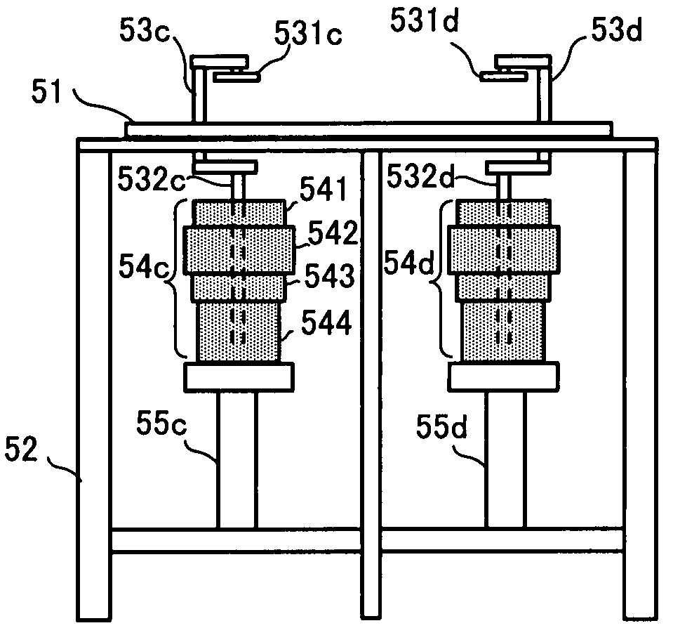
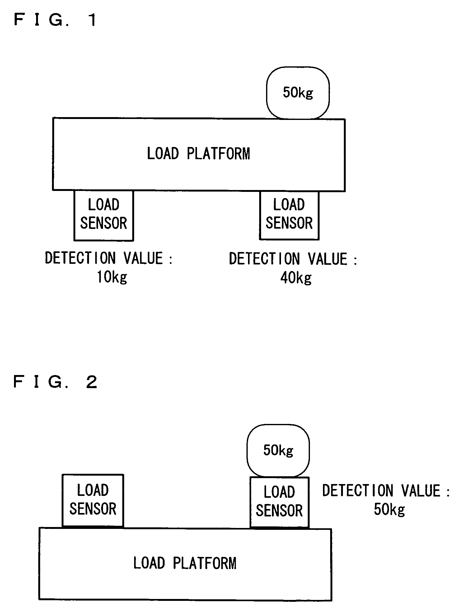
[0085]Firstly, a principle of a weight applying / calibration method according to a first embodiment will be described. As shown in FIG. 1, in a conventional weight applying / calibration method in which a weight is placed on a load platform with a plurality of load sensors (i.e., leg portions) of a weight measuring apparatus facing downward, one load is distributed among the plurality of load sensors, and thus a proper calibration cannot be performed. On the other hand, according to the present invention, instead of performing a calibration by placing a weight on the load platform so as to indirectly apply weight to the load sensors, the calibration is performed by directly applying the weight to load sensor sections 12. That is to say, as shown in FIG. 2, the calibration is performed by applyi...

second embodiment

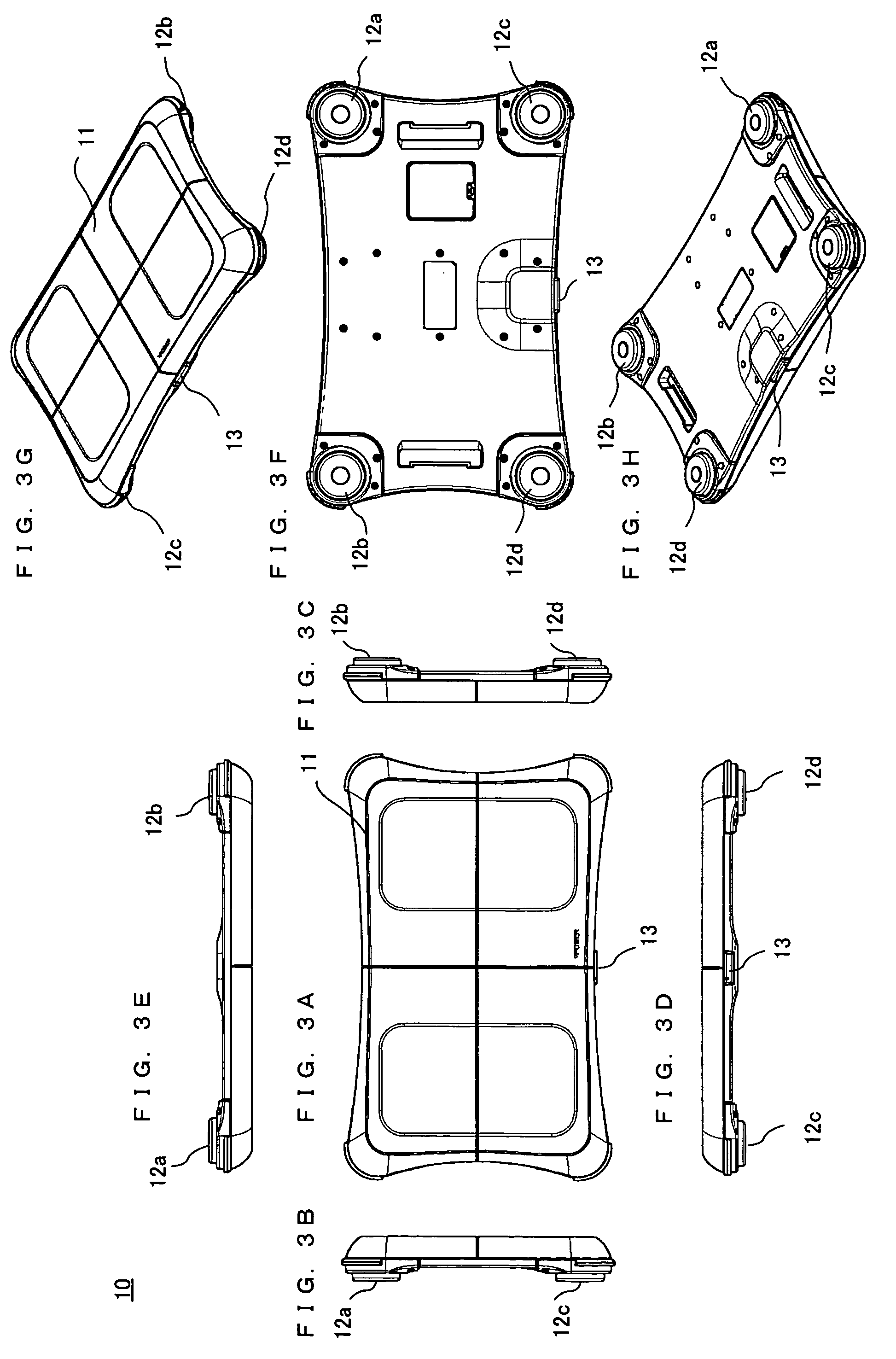
[0115]Next, a second embodiment of the present invention will be described with reference to FIGS. 10 to 16. In the first embodiment described above, a load of the weight 54 is applied to each of the load sensor sections 12 so as to perform a calibration. In the case where the calibration is performed in such a manner as described above, a measurement error can be substantially suppressed as compared to when using a conventional calibration method. However, under actual usage conditions, in the case where the weight measuring apparatus 10 is mounted in the place of use and a person, for example, steps onto the load platform 11, the load platform 11 is more or less deflected due to the weight of the person, as shown in FIG. 10. That is, the frame 15 forming the weight measuring apparatus 10 is deformed due to the weight of the person, and each of load sensor sections 12 is accordingly slightly inclined in its entirety. As a result, as shown in FIG. 11, the load cell 23 is to be accor...


PUM

PropertyMeasurementUnit
weightaaaaaaaaaa
weightaaaaaaaaaa
weightaaaaaaaaaa

Abstract

A weight measuring apparatus, in which a load platform is supported by a plurality of load sensor sections and the weight of a measurement target object placed on the load platform is measured based on a load value detected by each of the plurality of load sensor sections, is supported by a support section. Thereafter, the weight applying section applies a predetermined load to each of the plurality of load sensor sections included in the supported weight measuring apparatus.

Description

CROSS REFERENCE TO RELATED APPLICATION[0001]The disclosure of Japanese Patent Application No. 2007-283445, filed Oct. 31, 2007, is incorporated herein by reference.BACKGROUND OF THE INVENTION[0002]1. Field of the Invention[0003]The present invention relates to a calibration of a weight measuring apparatus, and more particularly to a weight applying unit for performing a calibration on a weight measuring apparatus comprising a plurality of load sensors and a weight applying method of performing the same.[0004]2. Description of the Background Art[0005]In a weight measuring apparatus, using a load sensor, which is typified by a scale or the like, a calibration is performed on a load sensor-integrated weight measuring apparatus as a finished product, in order to improve an accuracy of measurement results. As a calibration method used for a weight measuring apparatus using a single load sensor, for example, a specific load of a weight is placed on a load platform at a center position the...

Claims


Application Information

Patent Timeline
Patent Type & Authority Applications(United States)
IPC IPC(8): G01L25/00
CPCA63F2300/1056A63F2300/1062G01G23/01G01G19/44G01G21/22A63F2300/8005
Inventor YAMAZAKI, HITOSHINAGAREDA, TAKESHIUMEKAWA, MASAHIKOICHIKAWA, RYUJIMORI, TAKESHITAKEDA, KAZUHIRO
Owner NINTENDO CO LTD
Why Eureka
Try Eureka