Trigger Switch Mechanism for Nail Gun

a switch mechanism and nail gun technology, applied in the direction of nailing tools, manufacturing tools, stapling tools, etc., can solve the problems of inconvenient operation of the switch button, easy accidental danger of shooting, and inability to hit the nail

Inactive Publication Date: 2009-04-30
ROBERT BOSCH TOOL +1
View PDF36 Cites 42 Cited by
  • Summary
  • Abstract
  • Description
  • Claims
  • Application Information

AI Technical Summary

Benefits of technology

[0009]An object and effect of the present invention is carried out through the following technology means. A switch mechanism for a nail gun includes a trigger valve formed on the nail gun; a safety slidable rod configured to push against a workpiece and indirectly drive the trigger valve; a main trigger arranged between the safety slidable rod and the trigger valve; an outer trigger arranged on an outer side of the main trigger; and an inner trigger disposed in the main trigger for touching the trigger valve to switch on, wherein the main trigger drives the inner trigger to move upwards or away from a touchable position for the safety slidable rod, thereby performing a sequential actuation mode; wherein the outer trigger can drive the inner trigger to make the inner trigger hold in a position where the safety slidable rod can touch the inner trigger, thereby performing a contact actuation mode. Hereby, it is very convenient to selectively switch the sequential actuation mode and the contact actuation mode when the main trigger is pressed or released.
[0010]In addition, the present invention further includes a first elastic member disposed between the trigger valve and the main trigger or inner trigger for driving the inner trigger to lift up or be away from a touchable position for the safety slidable rod. An adjusting base is pivotally mounted on the main trigger, the inner trigger is pivotally mounted on the adjusting base, and the outer trigger can drive the adjusting base to swing,

Problems solved by technology

However, if the operator inadvertently presses the main trigger and erroneously touches the safety slidable rod or the hitting base, accidentally dangerous shot easily happens.
However, when the sequential actuation mode is selected, if an operator first pulls the main trigger, and then arranges the safety slidable rod or the hitting base to press on a workpiece, thus, the trigger lever may not be driven by the rotating rod which is d

Method used


Image

  • Trigger Switch Mechanism for Nail Gun
  • Trigger Switch Mechanism for Nail Gun
  • Trigger Switch Mechanism for Nail Gun

Examples


Embodiment Construction

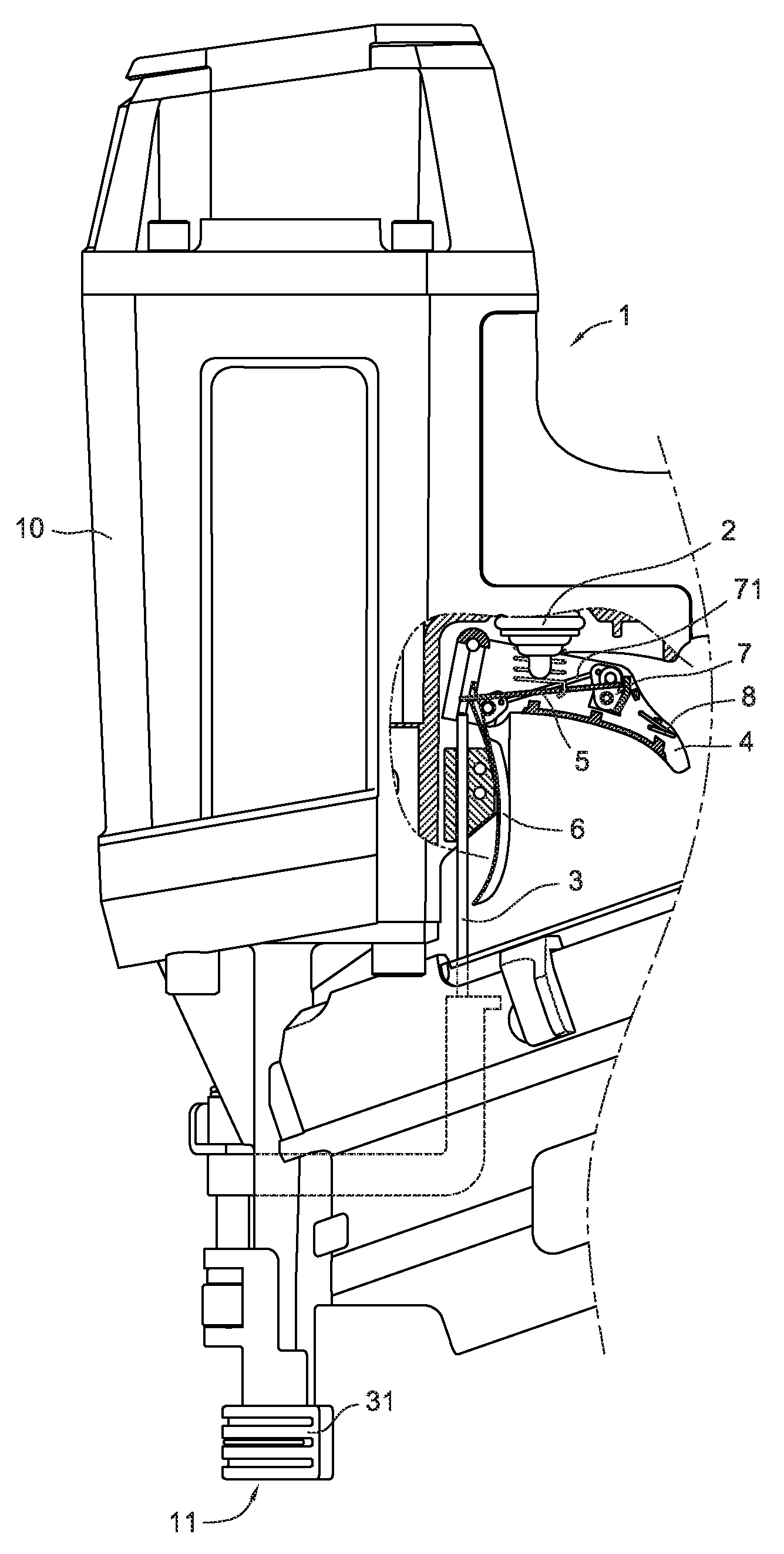
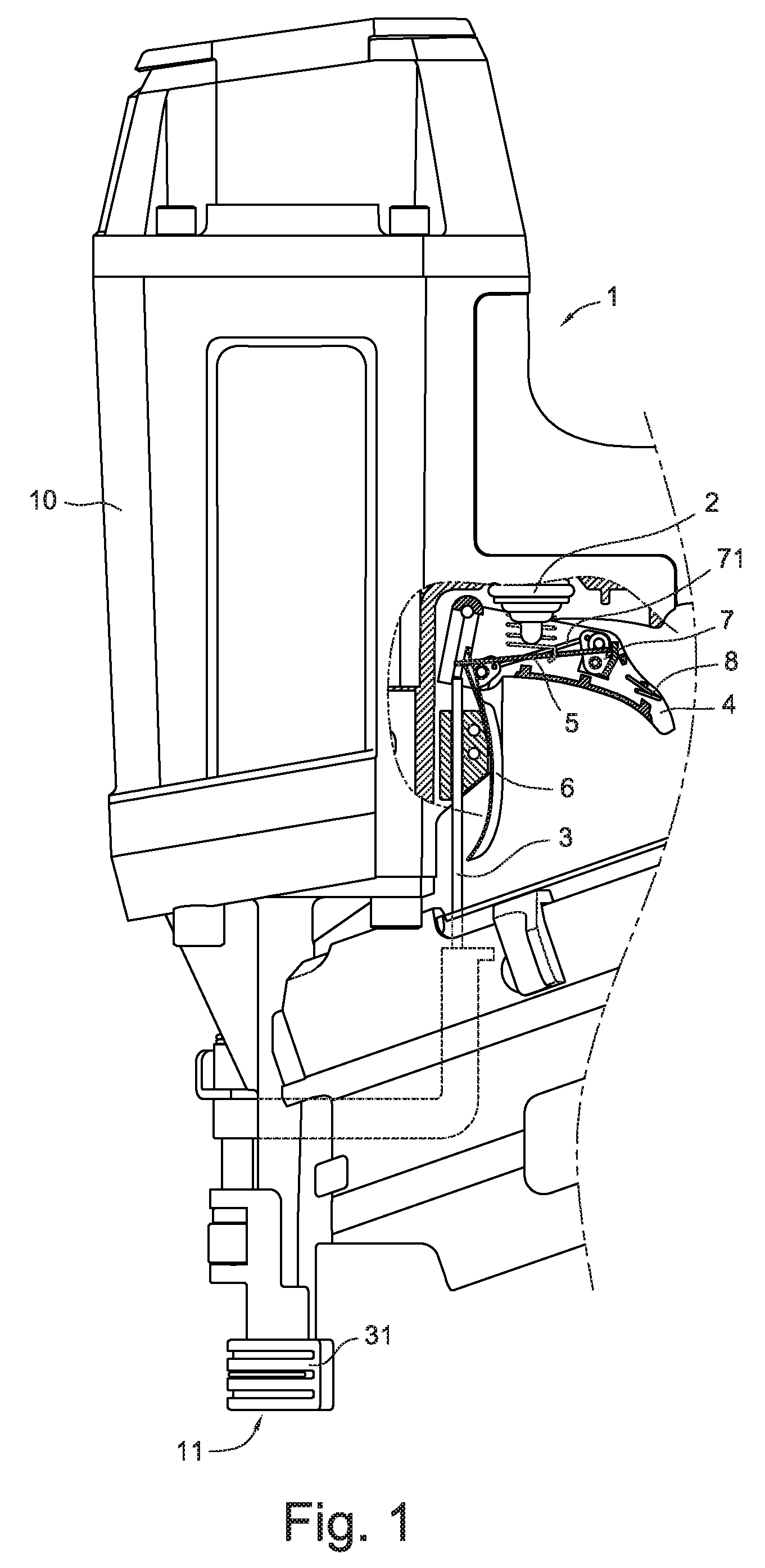
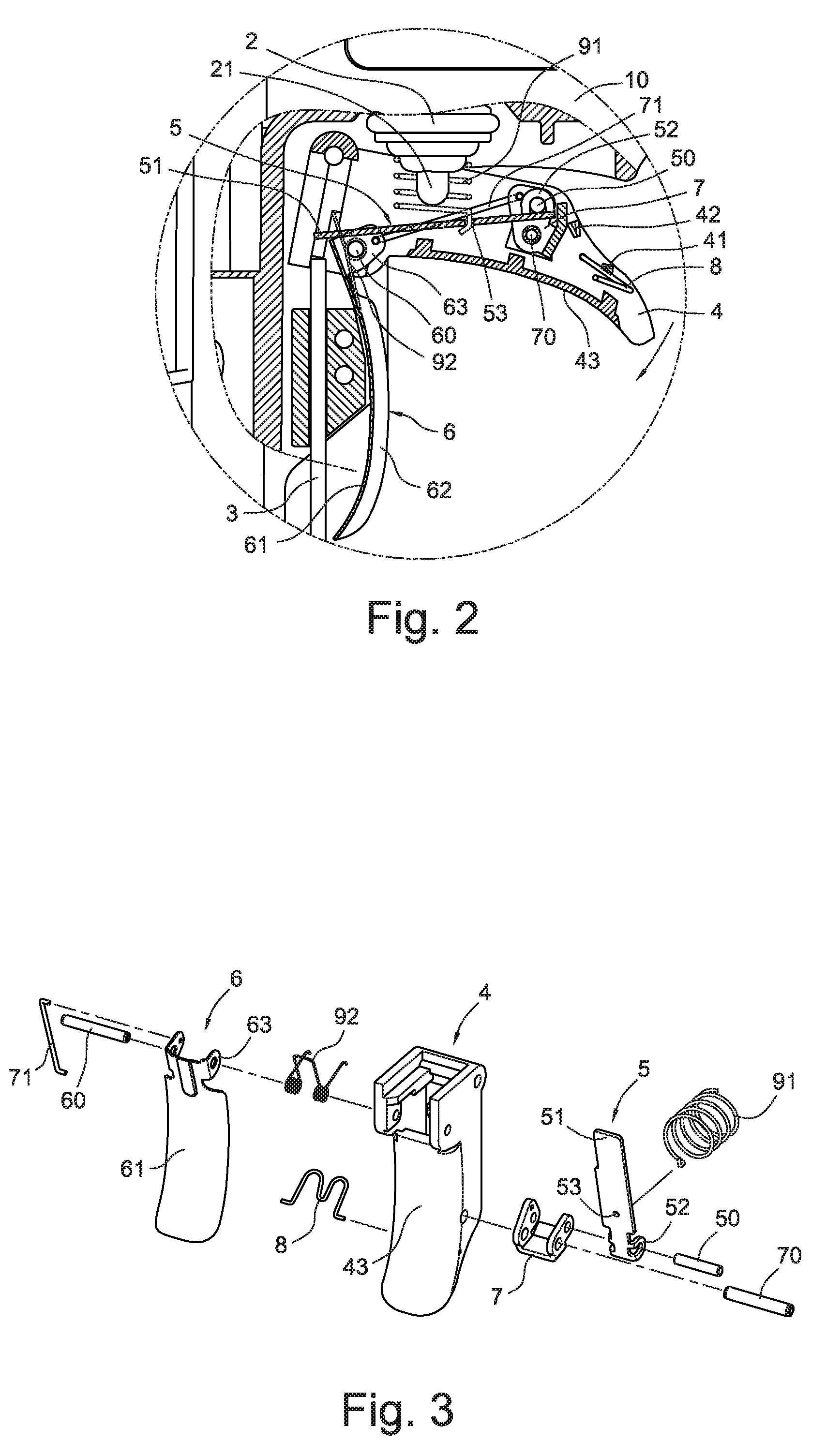
[0023]Referring to FIGS. 1 to 3, a trigger switch mechanism for a nail gun in accordance with an exemplary embodiment of the present invention is shown. A trigger valve 2 which is configured for driving to hit a nail, is formed in a housing 10 of a nail gun 1. A safety slidable rod 3 is configured to push against a workpiece and indirectly drive the trigger valve 2. A main trigger 4 is pivotally arranged in the housing 10 and located between the trigger valve 2 and the safety slidable rod 3. An inner trigger 5 is pivotally disposed in the main trigger 4 to touch the trigger valve 2 to switch on. The main trigger can drive the inner trigger to lift up or disengage from the safety slidable rod 3 to a touchable position for the safety slidable rod 3 (referring to FIGS. 4 and 5).

[0024]According to the above-mentioned, an outer trigger 6 is pivotally mounted on the housing 10 outside the main trigger 4 or an outer side surface of the main trigger 4 via a first shaft 60 thereon, as illust...


PUM

PropertyMeasurementUnit
Elasticityaaaaaaaaaa

Abstract

A trigger switch mechanism for a nail gun includes a trigger valve formed on the nail gun for trigger nail shooting, a safety slidable rod configured to push against a workpiece and indirectly drive the trigger valve, a main trigger arranged between the safety slidable rod and the trigger valve, and an inner trigger disposed in the main trigger for touching the trigger valve to switch on the trigger valve. The main trigger drives the inner trigger to extend to or to leave a touchable position of the safety slidable rod, and thereby the nail gun performs in a sequential actuation mode. An outer trigger is arranged on an outer side of the main trigger for driving the inner trigger to hold the inner trigger at a position where the safety slidable rod can touch the inner trigger, and thereby the nail gun performs in a contact actuation mode.

Description

BACKGROUND[0001]The present invention relates to a trigger switch mechanism for a nail gun, and more particularly to a trigger switch mechanism which includes a main trigger and an outer trigger disposed outside the main trigger to control movement of an inner trigger, thereby switching the nail gun operation in a sequential actuation mode, or a contact actuation mode.[0002]A pneumatic nail gun is a type of tool used to drive nails into wood or some other kind of material by a hitting rod which is driven by compressed air. Movement of the hitting rod is cooperatively controlled by a safety slidable rod, a trigger valve, a main trigger, and an inner trigger disposed on a gun body.[0003]Actuating nails for a pneumatic nail gun can generally be divided into two kinds, one is the sequential actuation mode (or the restrictive mode) and the other is the contact actuation mode.[0004]In the sequential actuation mode, an operator should first set a safety slidable rod or a hitting base on th...

Claims


Application Information

Patent Timeline
IPC IPC(8): B27F7/30
CPCB25C1/008
Inventor HUANG, CHI-SHENG
Owner ROBERT BOSCH TOOL
Why Eureka
Try Eureka