Electrostatic Coating System

a coating system and electrostatic technology, applied in the direction of electrostatic spraying apparatus, spraying power supply, burners, etc., can solve the problems of high voltage leakage, increase degrade the coating quality of work, etc., to prevent excessive high voltage leakage, reduce the cost of additional use of grounded electrodes, and quick cope with the situation

a coating system and electrostatic technology, applied in the direction of electrostatic spraying apparatus, spraying power supply, burners, etc., can solve the problems of high voltage leakage, increase degrade the coating quality of work, etc., to prevent excessive high voltage leakage, reduce the cost of additional use of grounded electrodes, and quick cope with the situation

US20090108109A1Active Publication Date: 2009-04-30TOYOTA JIDOSHA KK +1

Image

  • Electrostatic Coating System
  • Electrostatic Coating System
  • Electrostatic Coating System

Examples


first embodiment

[0057]In the electrostatic coating system according to the present invention, the control panel 13 does double controls of the high voltage from two different aspects. The first high voltage control is such that the work current I5 is controlled in a substantially automatic manner. An example of this control is shown in the flowchart in FIG. 5. The second mode of high voltage control is such that the leak current I2 is controlled in a substantially automatic manner, of which an example is specifically shown in the flowchart in FIG. 6.

[0058]The example of the first mode of high voltage control is explained below with reference to the flowchart of FIG. 5. In step S1 of the flow, a first threshold Ia is acquired. In the next step S2, a total current I1, total leak current I2 and output high voltage value Vm are acquired.

[0059]In the next step S3, the control panel 13 determines a current I5 flowing through the leak current to be coated by calculating I1, I2 and Vm acquired in step S2 o...

second embodiment

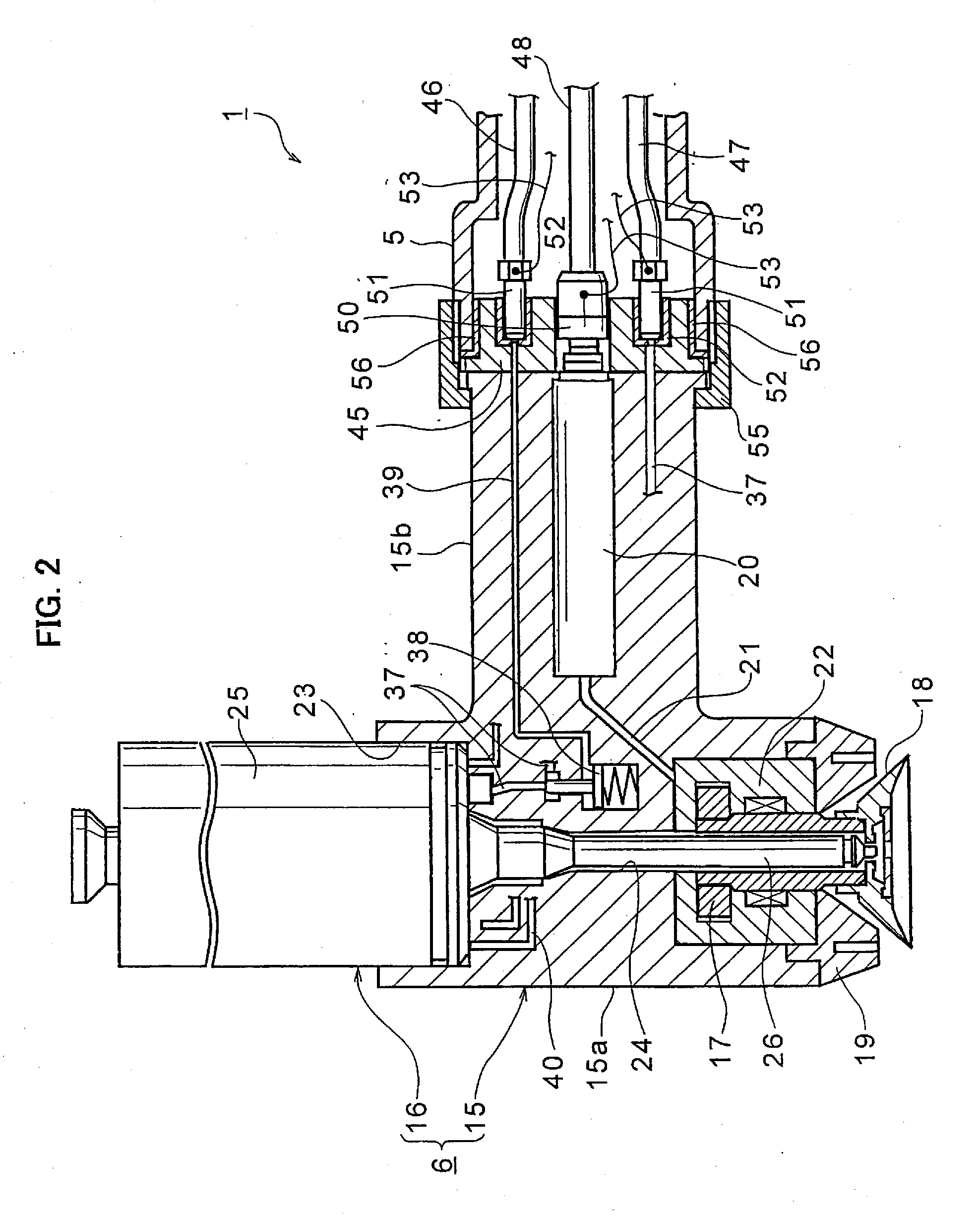
[0072]With reference to FIG. 7, in the coating robot 81 including the atomizer the distal end of the wrist portion 5 made of stainless steel is located nearer to the bell head 18 than the end plate 45 of the atomizer 6. Accordingly, first and second two circular extension rings 84 and 85 made of stainless steel and electrically conductive are additionally provided on an outer margin or circumferential portion of the end plate 45. Thus, the outer margin or circumferential portion of the end plate 45 is extended toward the bell head 18 beyond the distal end of the wrist portion 5. That is, the first and second conductive extension rings 84 and 85 act as conductive extension members for extending the outer margin of the end plate 45 toward the bell head 18.

[0073]By extending the marginal portion or outer circumferential portion of the end plate 45 with the use of the first and second conductive rings 84 and 85 toward the bell head 18 beyond the distal end of the wrist portion 5, if an...


PUM


Abstract

An electrostatic coating system includes a coating robot (1) and an electrostatic atomizer (6) attached to a polyarticular wrist portion (5) of the robot (1). The atomizer (6) includes an end plate (45), metallic connector (50) fixed to the end plate (45) in electric conduction, high voltage generator (20) and bell head (18). Electric power is supplied to the high voltage generator (20) through the connector (50). Wires (53) are connected to the connector (50) to take out high voltage leak caused by contamination like a deposition of paint on outer surfaces of the atomizer (6) through the wires 53 to control the high voltage generator (20) to lower the value of the high voltage applied to the bell head (18) of high voltage leak detected through the wires (53) is larger than a predetermined threshold value.

Description

FIELD OF THE INVENTION[0001]The present invention generally relates to an electrostatic coating system, and more particularly, to an electrostatic coating system including an electrostatic atomizer attached to an arm of a coating robot.BACKGROUND OF THE INVENTION[0002]Electrostatic atomizers are devices for applying atomized and electrically charged paint onto work pieces due to electrostatic attraction under an electrostatic field generated by application of a high voltage. Because they use such a high voltage, leakage of the high voltage is one of important issues of electrostatic atomizers and electrostatic coating systems including such electrostatic atomizers.[0003]In Japanese Patent Laid-open Publication No. JP H10(1998)-109054, it is pointed out that a deposition of paint on the outer surface of an electrostatic atomizer may act to bring about a high voltage leak or, when fragments of the deposit of paint from the outer surface of the atomizer happen to adhere onto a work, th...

Claims


Application Information

Patent Timeline
30 Apr 2009
Publication
US20090108109A1
IPC
B05B5/025
CPC
B05B5/0407; B05B5/0426; B05B5/053; B05B5/0531; B05B15/025; B05B5/1675; B05B12/1463; B05B13/0431
Inventors
MORI, TAKANOBU; HONMA, KENGO