Occupant protection device of vehicle

Inactive Publication Date: 2009-04-30
MAZDA MOTOR
View PDF5 Cites 10 Cited by
  • Summary
  • Abstract
  • Description
  • Claims
  • Application Information

AI Technical Summary

Benefits of technology

[0018]According to another embodiment of the present invention, the groove portion is configured such that a rearward portion thereof lowers gradually. Thereby, a rear end portion of the lap-belt pre-tensioner can be prevented from projecting upward from the side sill so that the lap-belt pre-tensioner can be prevented more properly from projecting into the ingress-egress opening.
[0019]According to another embodiment of the present invention, a wall face of the groove portion has a specified shape which can temporally fix the lap-belt pre-tensioner into the groove portion. Thereby, the temporal fixing of the lap-belt pre-tensioner can be achieved by merely inserting the lap-belt pre-tensioner into the groove portion, thereby improving an attachment.
[0020]According to another embodiment of the present invention, a retractor operative to wind up one end of the shoulder belt and a shoulder-belt pre-tensioner operative to draw in the shoulder belt are disposed above and on the outside of the lap-belt pre-tensioner so as to be covered with a pillar trim, which covers the inside of the pillar, from the inside of the vehicle compartment. Thereby, the pillar can be prevented from projecting toward the inside of the vehicle compartment due to providing the retractor and the shoulder-belt pre-tensioner. Further, since the lap-belt pre-tensioner is inserted into the groove portion formed on the upper face of the projecting portion of the side sill, it can be properly located in a dead space beside the seat along the side sill. Thus, the lap-belt pre-tensioner, the shoulder-belt pre-tensioner, and the retractor can be properly disposed without narrowing the space of the vehicle compartment.
[0021]According to another embodiment of the present invention, the pillar is comprised of a plurality of panels which have a flange at least one end thereof in the longitudinal direction, a seaming welt is provided at the pillar so as to cover the flanges of the plural panels overlapped with each other, a pillar trim is provided so as to cover the inside of the pillar, the lower support member and the lap-belt pre-tensioner are provided at or near a lower end portion of the pillar, the lap-belt pre-tensioner is covered with the pillar trim from the inside of the vehicle compartment, and the pillar trim includes a through hole, through which a member extending from the lap belt to the lap-belt pre-tensioner or the lap belt itself extend, a notch which is provided so as to extend from the through hole to one end of the pillar trim in the longitudinal direction, and a fixed portion which is fixed at least to an upper peripheral portion of the seaming welt above an end portion of the notch and a lower peripheral porti

Problems solved by technology

Herein, while it is considered that the lap-belt pre-tensioner is disposed on an upper face of the projecting por

Method used


Image

  • Occupant protection device of vehicle
  • Occupant protection device of vehicle
  • Occupant protection device of vehicle

Examples


Example

Embodiment 1

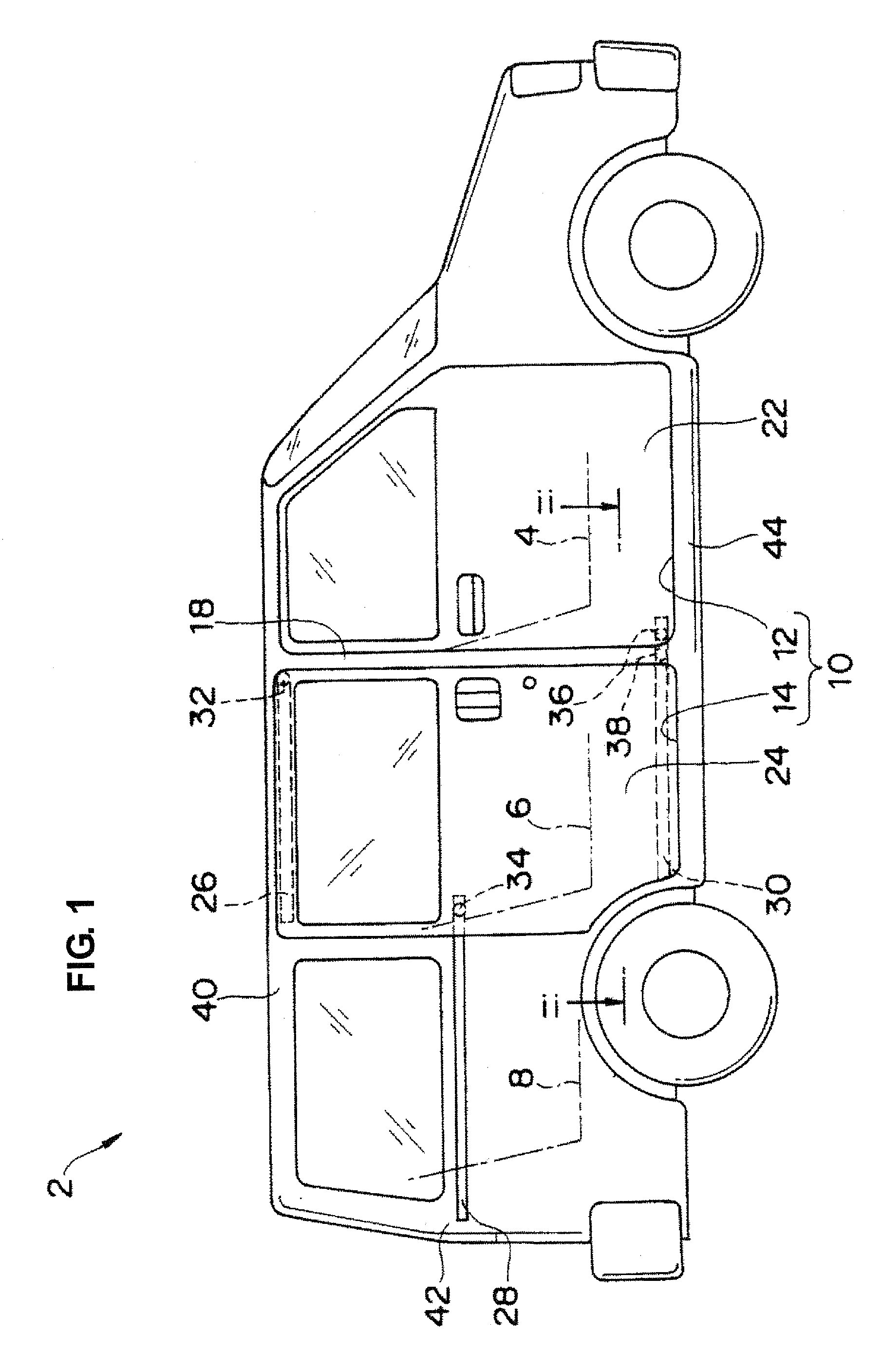
[0044]FIG. 1 is a schematic diagram of a vehicle 2 equipped with an occupant protection device according to a first embodiment of the present invention.

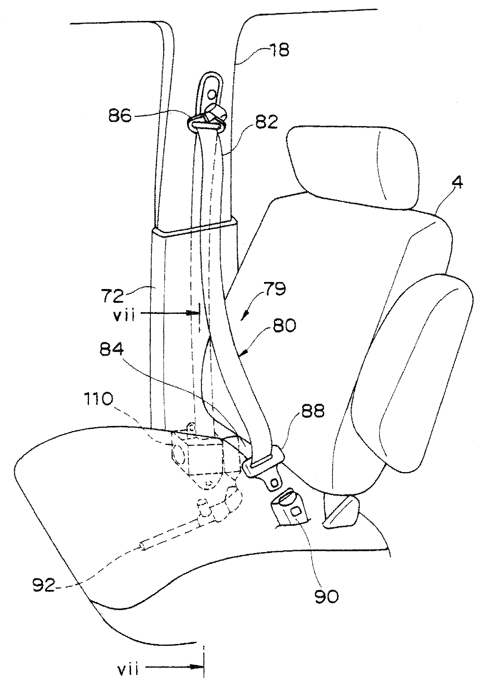
[0045]In the present embodiment, the vehicle 2 comprises a first row seat 4, a second row seat 6 and a third row seat 8. Herein, the “front seat” indicates the first row seat 4, and the “rear seat” indicates the second row seat 6 and the third row seat 8.

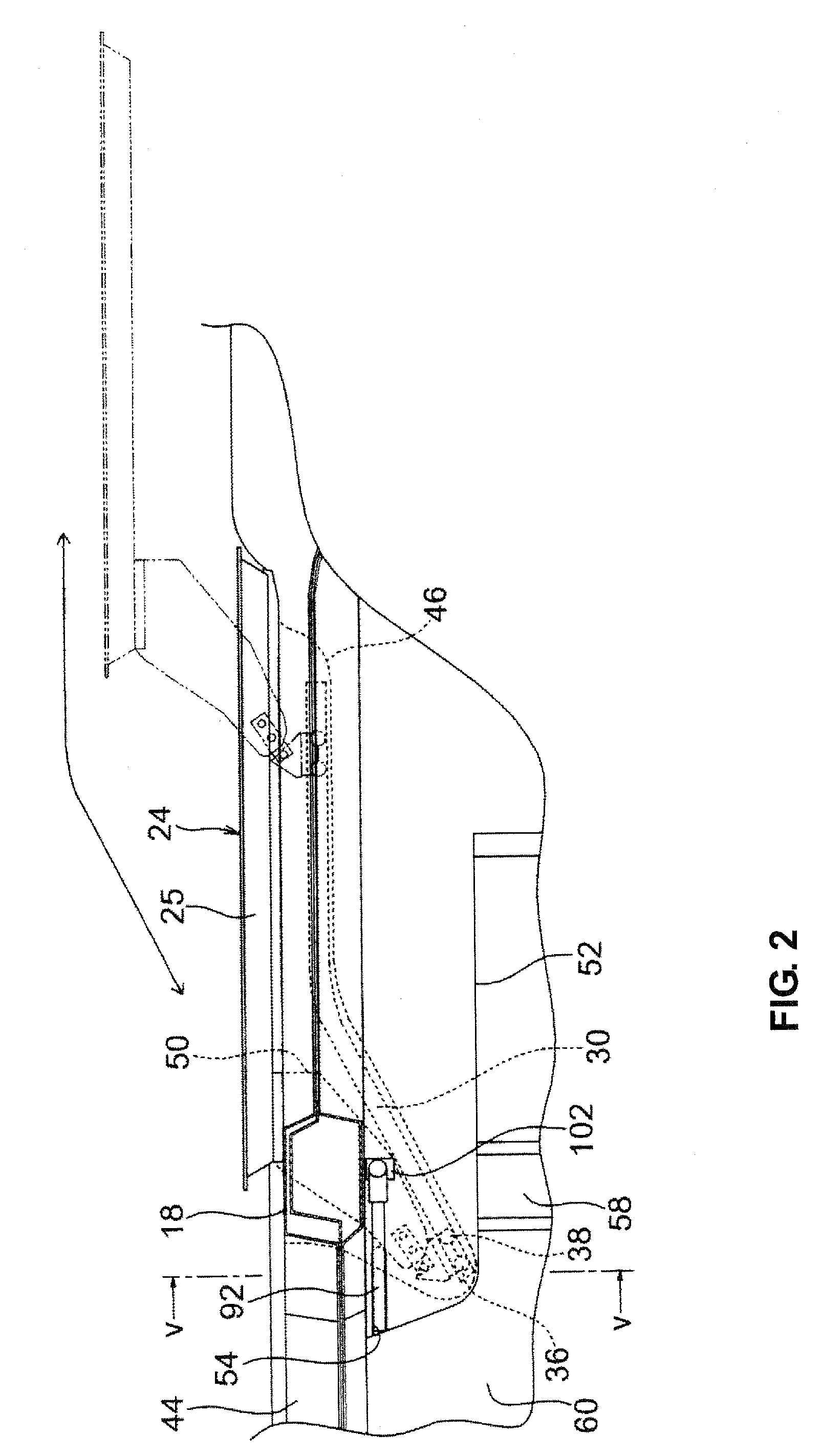
[0046]A pair of side sills 44 is provided so as to extend on both sides of a vehicle floor, and an ingress-egress opening 10 is formed above a side sill 44. The ingress-egress opening 10 is separated into a front opening (ingress-egress opening for the front seat) 12 and a rear opening (ingress-egress opening for the rear seat) 14 by a center pillar 18 which extends upward from a specified portion of the side sill 44 near the front seat 4. The front opening 12 for the front seat can be closed by a hinge door 22 and the rear opening 14 for the rear seat can be closed by a ...

Example

[0066]FIGS. 11-18 shows an occupant protection device according to a second embodiment of the present invention. Hereinafter, the same structure / components of the second embodiment as those of the above-described first embodiment are denoted by the same reference characters, specific descriptions of which will be omitted.

Example

[0067]The difference of the present embodiment from the above-described first embodiment is that a lap-belt pre-tensioner 92′ is disposed on the upper face of the projecting portion 52 so as to extend rearward from the disposition portion of the lower support member 102, not extending forward.

[0068]Likewise, the lap-belt pre-tensioner 92′ comprises a substantially cylindrical-shaped cylinder 93′, a piston (not illustrated) accommodated in the cylinder 93′, a gas generator, such as a powder, accommodated in the cylinder 93′, and an igniter 95′ to ignite the gas generator.

[0069]Meanwhile, as shown in FIG. 18, a groove portion 54′ to accommodate a tip portion of the lap-belt pre-tensioner 92′, which is formed on the upper face of the projecting portion 52, is provided at a position which is rearward from the center pillar 18. Accordingly, a specified portion which is located from the center to the rear end of the pre-tensioner 92′ inserted into the groove portion 54′ is disposed rearwa...


PUM


Abstract

A lap-belt pre-tensioner operative to draw in a lap belt is disposed on an upper face of a projecting portion so as to extend in a longitudinal direction of a vehicle from an disposition portion of a lower support member, and on the upper face of the projecting portion is provided a groove portion so as to accommodate the lap-belt pre-tensioner in such a manner that the lap-belt pre-tensioner substantially does not project into an ingress-egress opening. Accordingly, there can be provided an occupant protection device of a vehicle equipped with a slide door in which the lap-belt pre-tensioner does not project into the ingress-egress opening.

Description

BACKGROUND OF THE INVENTION[0001]The present invention relates to an occupant protection device of a vehicle which is equipped with a three-point seatbelt.[0002]The three-point seatbelt includes a shoulder belt operative to support an occupant by extending obliquely from a shoulder to a waist of the occupant and a lap belt operative to protect the occupant by extending laterally over the waist of the occupant. A pre-tensioner operative to draw in the seatbelt at a vehicle collision is generally attached to an end portion of the shoulder belt of the three-point seatbelt. Herein, the pre-tensioner operates at the vehicle collision so that the shoulder belt is mainly pulled so as to press the occupant against the seat properly.[0003]Japanese Utility-Model Publication No. 53-35850 proposed a technology in which in addition to a pre-tensioner which is connected to an end portion of the shoulder belt (shoulder-belt pre-tensioner), another pre-tensioner which is connected to an end portion...

Claims


Application Information

Patent Timeline
IPC IPC(8): B60R22/04B60R22/34
CPCB60R13/025B60R22/4604B60R22/1952B60R22/1951
Inventor HIROTANI, YASUNARI
Owner MAZDA MOTOR
Why Eureka
Try Eureka