Interphase insulating sheet of rotating electric machine, and electric compressor

a technology of rotating electric machines and insulating sheets, which is applied in the direction of machines/engines, positive displacement liquid engines, pumping/engines, etc., can solve the problems of damage to the edges of the coupling pieces might be torn off, and the insulating coating of the coil might be damaged

Inactive Publication Date: 2009-04-30
TOYOTA IND CORP
View PDF3 Cites 13 Cited by
  • Summary
  • Abstract
  • Description
  • Claims
  • Application Information

AI Technical Summary

Benefits of technology

[0004]Accordingly, it is an objective of the present invention to provide an interphase insulating sheet of a rotating electric machine that prevents coils to be inserted from getting caught by the edges of bridge pieces or the edge of the insulating sheet, and an electric compressor.

Problems solved by technology

In this case, the insulating coating of the coils might be damaged or the edges of the coupling pieces might be torn off.
In this case, the insulating coating of the coil might be damaged.

Method used


Image

  • Interphase insulating sheet of rotating electric machine, and electric compressor
  • Interphase insulating sheet of rotating electric machine, and electric compressor
  • Interphase insulating sheet of rotating electric machine, and electric compressor

Examples


Embodiment Construction

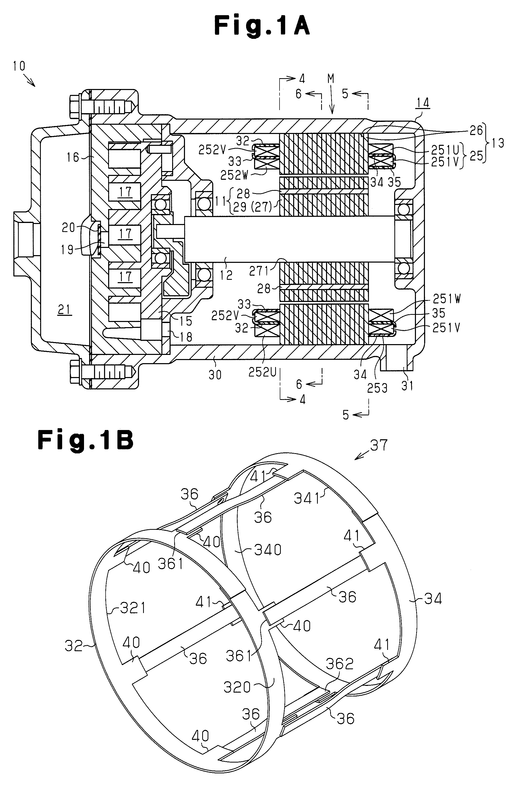
[0034]An electric compressor 10 according to a first embodiment of the present invention will now be described with reference to FIGS. 1A to 9B. In the description of this specification, the front side and the rear side correspond to the left side and the right side, respectively, in FIG. 1A.

[0035]The electric compressor 10 shown in FIG. 1A is a scroll electric compressor. A rotating electric machine M of the electric compressor 10 includes a rotor 11, a rotary shaft 12, a stator 13, a motor housing 14, a compression operation body, which is a movable scroll 15 in this embodiment, and a fixed scroll 16. The rotor 11 is fixed to the rotary shaft 12, and the stator 13 is securely fitted to the inner circumferential surface of the motor housing 14. The movable scroll 15 orbits about the axis of the rotary shaft 12 as the rotary shaft 12 is rotated. When the movable scroll 15 orbits, compression chambers 17 between the movable scroll 15 and the fixed scroll 16 move in the direction of r...


PUM


Abstract

An interphase insulating sheet of a rotating electric machine is disclosed. The interphase insulating sheet includes a first insulating portion arranged between first coil ends of two different phases, a second insulating portion arranged between second coil ends of two different phases, and bridge pieces inserted in slots. The first insulating portion includes a first coupling aid. The second insulating portion includes a second coupling aid. The first coupling aid and the second coupling aid each includes an outer surface facing radially outward of the stator core and an inner surface facing radially inward of the stator core. The first end portion of the bridge piece is located on the outer surface of the first coupling aid, and the second end portion of the bridge piece is located on the inner surface of the second coupling aid.

Description

BACKGROUND OF THE INVENTION[0001]The present invention relates to an interphase insulating sheet of rotating electric machine, and an electric compressor.[0002]Japanese Laid-Open Patent Publication No. 58-119739 discloses an interphase insulating sheet arranged between the ends of the coil of one phase and the ends of the coils of the other phases. The interphase insulating sheet disclosed in the above publication includes a pair of coil end insulating portions, which insulate the coil ends from each other, and coupling pieces (bridge pieces), which are inserted in slots of a stator. The pair of coil end insulating portions and the coupling pieces are formed separately, and both ends of each coupling piece are heat welded to the pair of coil end insulating portions.[0003]The coils, which is wound around the stator by wave winding, are inserted in the slots using an inserter as disclosed in, for example, Japanese Laid-Open Patent Publication No. 2005-80356. In a case where the coupli...

Claims


Application Information

Patent Timeline
Patent Type & Authority Applications(United States)
IPC IPC(8): H02K3/38F04D25/06
CPCH02K3/38H02K3/34
Inventor HORIBA, TATSUYAFUKASAKU, HIROSHI
Owner TOYOTA IND CORP
Why Eureka
Try Eureka