
Shoe structure and fabricating method of the same

Inactive Publication Date: 2009-05-07
CHANG YING NAN
View PDF0 Cites 8 Cited by
  • Summary
  • Abstract
  • Description
  • Claims
  • Application Information

AI Technical Summary

Benefits of technology

[0008]The present invention provides a new and improved shoe structure comprising: at least an upper, an insole and an outsole. The lower edge of the upper is formed with a plurality of teeth-like extensions, and the insole has a plurality of slits for allowing the teeth-like extensions to pass therethrough thereby to be glued and bonded with the outsole. The shoe structure further includes a peripheral shielding band which can be bonded and / or stitched at the lower end of the upper portion to avoid rain, liquid or water flowing into the underside of the sole via the slits and the teeth-like extensions.
[0017]As the shoe structure of the present invention does not include a midsole, this may improve the softness and comfortability of the shoe; further, due to the peripheral shielding band is covered on the edge slits, this would prevent the rain or water from penetrating into the sole via the edge slits. Accordingly, the method and the shoe structure can eliminate the drawbacks of the above-mentioned traditional shoes.

Problems solved by technology

The upper portion of Vlasak is formed with a plurality of slits for permitting the teeth-like extensions of the insole passing therethrough, therefore the rain, water and some liquids may flow into the underside of the insole via the slits; this always cause the shoe become mildewed and shorten the durability of the shoe.
Further, the Vlasak shoe structure needs more cost to apply the glue for bonding the insole, midsole and out sole in its due assembly process.

Method used


Image

  • Shoe structure and fabricating method of the same
  • Shoe structure and fabricating method of the same
  • Shoe structure and fabricating method of the same

Examples


Embodiment Construction

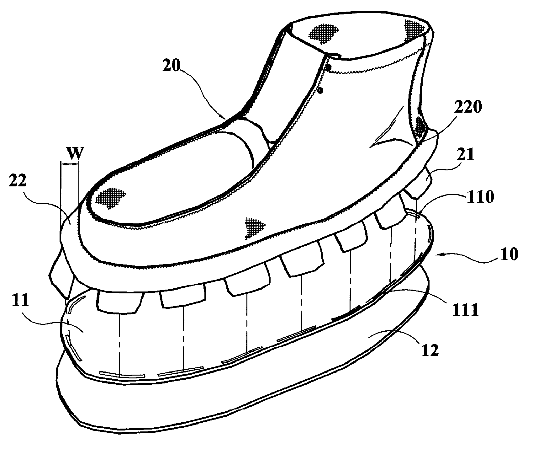
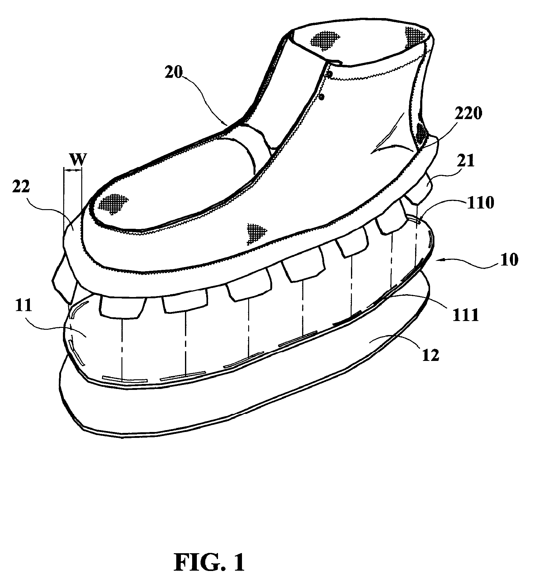
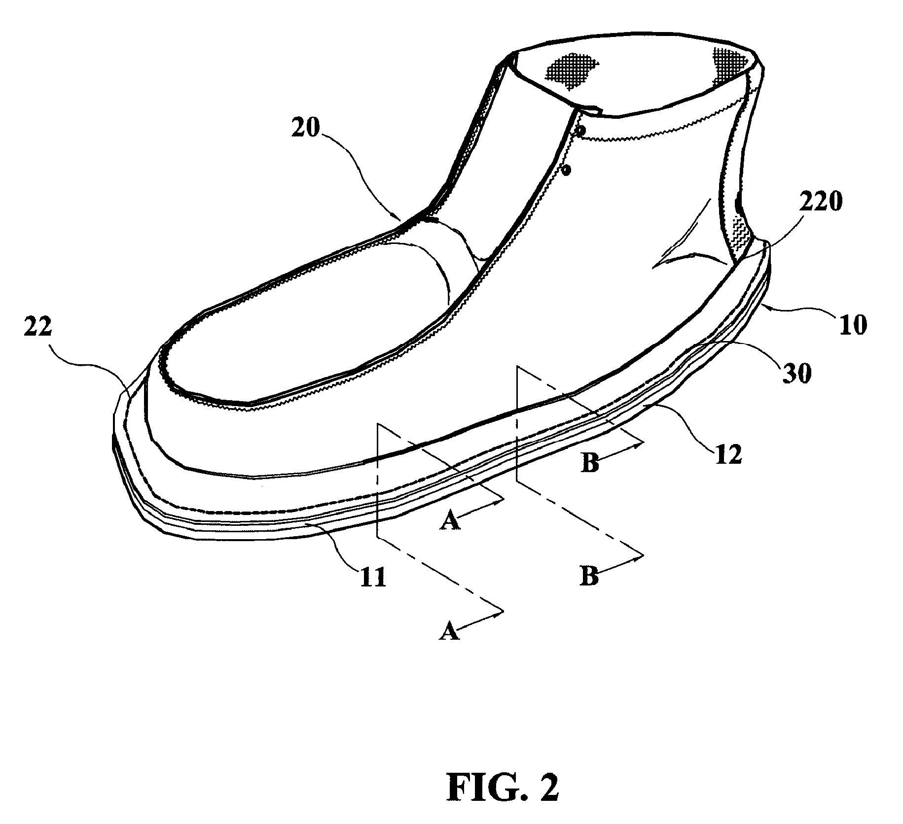
[0027]Referring to FIGS. 1 to 4, a shoe structure embodiment according to the present invention includes a sole 10 and an upper 20. The sole 10 includes at least an insole 11 and an outsole 12. The sole 10 maybe made of leather, plastic foaming material, such as EVA or the like.

[0028]The lower edge of the upper 20 is formed with a plurality of teeth-like extensions 21, and the peripheral edge 111 of the insole 11 is formed with a plurality of edge slits 110 for allowing the teeth-like extensions 21 to pass through thereby to be glued and bonded on the underside of the insole 11.

[0029]The shoe structure may further include a peripheral shielding band 22 which has a width W for connecting to the lower end of the upper portion 20 and the upper side of the peripheral edge 111 of the insole 11 by glue, adhesive and / or stitches 30 and 220 to cover the edge slits 110, so as to avoid rain, water, liquid or the like flowing into the sole 10 via the teeth-like extensions 21 and the edge slits...


PUM


Abstract

A method for fabricating a shoe which comprises at least an upper, an insole and an outsole. The lower edge of the upper is formed with a plurality of teeth-like extensions, and the insole has a plurality of slits for allowing the teeth-like extensions passing downward therethrough and to be glued and bonded with the outsole. The shoe structure may further include a peripheral shielding band stitched around the lower portion to avoid the rain, liquid or water running along the teeth-like extensions and penetrate through the slits.

Description

BACKGROUND OF THE INVENTION[0001]1. Field of the Invention[0002]The present invention relates generally to a shoe structure. More particularly, the present invention relates to a shoe structure which has an upper portion formed with a plurality of teeth-like extensions that penetrated the edge slits of an insole and covered by a peripheral shielding band.[0003]2. Description of the Related Art[0004]There are varieties of shoe structure that provides different function and fulfills specific purpose as being designed. Generally, the shoe structure includes an upper portion and a sole, wherein the upper portion covers the upper and sides of a foot, and the sole is connected to the lower end of the upper portion for supporting the foot of a shoe wearer.[0005]Typically, the shape of the upper portion is determined by a last. While the sole is connected with the upper portion, a last is fitted therebetween for fixing the shape that will make the upper portion to be shaped according to the...

Claims


Application Information

Patent Timeline
IPC IPC(8): A43B13/28A43B23/00A43D29/00
CPCA43B9/12
Inventor CHANG, YING-NAN
Owner CHANG YING NAN
Learn More