Air to air heat exchanger

a heat exchanger and air technology, applied in the direction of lighting and heating apparatus, heating types, laminated elements, etc., can solve the problems of limiting the power required to circulate the gas through the heat exchanger, and the kinetic energy change of the air is also limited to directional changes, so as to increase heat transfer and energy efficiency, and reduce cost

Inactive Publication Date: 2009-05-07
AZ EVAP
View PDF12 Cites 27 Cited by
  • Summary
  • Abstract
  • Description
  • Claims
  • Application Information

AI Technical Summary

Benefits of technology

[0045]The invention has the primary objective of producing a compact heat exchanger where air and other gases can be made to efficiently and cost-effectively exchange heat from one gas stream to another. The heat exchanger flat plates include features that support incorporation of a significant counterflow section with is the most effective heat transfer configuration. Additionally, the combination of flat plate configuration and flow channel arrangement provide the ability to incorporate multiple crossflow heat exchanger sections in series with the counter flow section. This takes advantage of the heat transfer surface in the inlet and exit channels in a manner that maximizes its heat transfer effectiveness. Material strips are incorporated to form the sides of these flow channels that allow channeling and directing the flow of air on each side of the heat transfer surface in patterns to maximize the heat exchangers effectiveness. These strips also maintain the gap between heat transfer plates and form the pressure boundary at the edge of the heat exchanger. The strips can be adhesively bonded to the plates if required to improve the pressure retaining capability and leak tightness of the heat exchanger boundary seal. The strips can be made of a wide range of materials with the material selected to match the needs of the application. Rounded strips are incorporated in the plates at the inlet and exit of the heat exchanger to limit the inlet and exit pressure losses and therefore limit the power required to circulate the gas through the heat exchanger. Mechanical clips are incorporated in strategic locations of each plate to locate, mechanically connect the plates, maintain the location of the strips, and aide in the distribution of heat exchanger internal loads.
[0046]The heat transfer of the heat exchange surface is enhanced using rounded dimples and protrusions arranged such that these occur on the top and bottom of the flow channel. The dimple and protrusion depth and diameter, imprint diameter, and composite pitch are set to yield the most effective heat transfer with the least pressure drop at heat exchanger velocities expected in the application. In particular, the diameter of the dimple and protrusion (the diameter of the spherical tool making the dimple impression) is set to yield boundary layer flow changes with minimal drag or pressure drop by having a diameter twice the diameter of the imprinted dimple. Namely, the imprint is a segment of the sphere with the inserted depth of approximately 7% of the sphere's diameter. This yields a dimple and protrusion surface that smoothly redirects the flow to create flow movement from the boundary layer to the bulk flow stream while offering little resistance to the air flow stream. The dimple and protrusion location and pitch are set such that a constant flow channel cross-sectional area is maintained both horizontally across the channel and longitudinally along the channel. By maintaining such a constant cross-sectional area additional entrance and exit losses (associated with gas movement through the dimpled area) are avoided. Air kinetic energy changes are also limited to directional changes rather than local velocity changes. The net effect is that the significant heat transfer improvement impact of the dimples and protrusions are realized without incurring the increase in friction factor and pressure drop common to other heat exchangers.
[0047]A primary objective of the present invention is to provide a sheet metal gas-to-gas heat exchanger that is simple to manufacture and assemble and has low pressure drop with dramatically improved heat transfer capabilities.

Problems solved by technology

Rounded strips are incorporated in the plates at the inlet and exit of the heat exchanger to limit the inlet and exit pressure losses and therefore limit the power required to circulate the gas through the heat exchanger.
Air kinetic energy changes are also limited to directional changes rather than local velocity changes.

Method used


Image

  • Air to air heat exchanger
  • Air to air heat exchanger
  • Air to air heat exchanger

Examples


Embodiment Construction

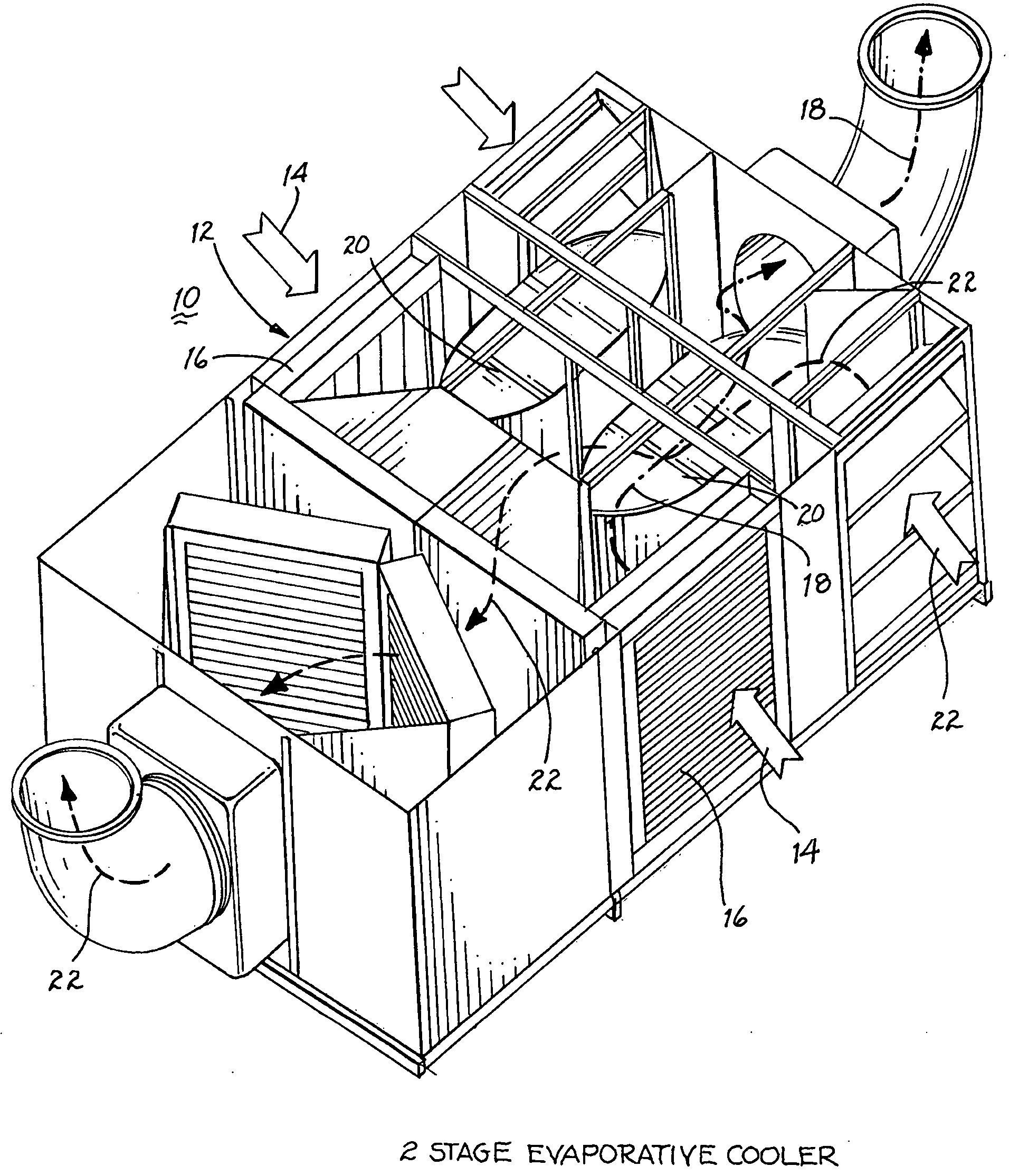
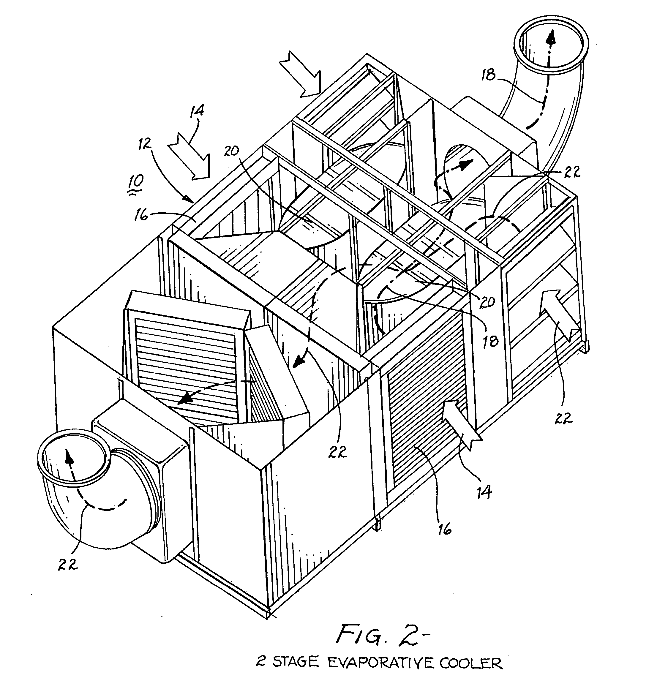
[0079]The preferred embodiment of the gas-to-gas (air-to-air) heat exchanger described herein is well suited for numerous applications over a broad range of thermal conditions by selective choice of the materials used for the parts and functions. Examples of such material selection are use of cast metal or graphite for the mechanical clips instead of injection molded plastic and graphite strips instead of plastic foam for the channel flow barriers and pressure boundaries. Additionally, many of the unique elements of the heat exchanger can be adapted or incorporated directly into other configurations to expand the set of applications. Given the need to narrow this broad range of applications in order to describe a preferred embodiment that demonstrates the benefits and allows effective characterization of the innovative features of this gas-to-gas heat exchanger, a two stage evaporative cooler application has been selected for the preferred embodiment. In this application, the gas to...


PUM


Abstract

A compact heat exchanger efficiently and cost-effectively exchanges heat from one gas stream to another through counter flow channels between parallel plates. Foam strips are incorporated to form the sides of the flow channels that allow channeling and directing the flow of air on each side of a plate heat transfer surface in patterns to maximize the heat exchanger's effectiveness and maintain the gap between heat transfer plates and form the pressure boundary at the edge of the heat exchanger. Clips are incorporated in strategic locations of each plate to locate and mechanically connect the plates to one another and to maintain the location of the foam strips. The heat transfer of the heat exchange surfaces are enhanced using rounded dimples and protrusions arranged such that these occur on the top and bottom of the flow channels.

Description

CROSS-REFERENCE TO RELATED APPLICATION[0001]The present application is related to and claims priority to a provisional application entitled “Air to Air Heat Exchanger” filed Nov. 2, 2007, assigned Ser. No. 60 / 985,165 and disclosing an invention by the present inventor.BACKGROUND OF THE INVENTION[0002]1. Field of the Invention[0003]The invention is directed to a flat plate air-to-air heat exchanger having a heat exchanger core formed by using gasket strips and interlocking clips to structurally join enhanced heat transfer surfaces. Uniquely shaped thin flat plate metal sheets create flow channels and heat transfer surfaces necessary to promote a combination of cross-flow and counter-flow heat exchange between two air streams to yield both a thermally efficient and cost-effective heat exchange configuration.[0004]2. Description of Related Art[0005]Heat exchangers, of which air-to-air heat exchangers are a subset, have been widely used in industrial processes, energy systems, and air c...

Claims


Application Information

Patent Timeline
Patent Type & Authority Applications(United States)
IPC IPC(8): F28D21/00
CPCF24F12/006F28D9/0037Y02B30/563F28F2275/085F28F2240/00F28F3/044Y02B30/56
Inventor KAMMERZELL, LARRY L.
Owner AZ EVAP
Why Eureka
Try Eureka