Coring Tool and Method

a coring tool and tool technology, applied in the field of oil and gas well drilling and the subsequent investigation of, can solve the problems of not necessarily performing lwd and mwd, and the drill string typically cannot be used to rotate the coring bit, and cannot provide the weight required

Active Publication Date: 2009-05-07
SCHLUMBERGER TECH CORP
View PDF23 Cites 31 Cited by
  • Summary
  • Abstract
  • Description
  • Claims
  • Application Information

AI Technical Summary

Problems solved by technology

Furthermore, LWD and MWD are not necessarily performed while the drill bit is actually cutting through the formation.
In sidewall coring, the drill string typically cannot be used to rotate the coring bit, nor can it provide the weight required to drive the bit into the formation.
Another challenge of sidewall coring relates to the dimensional limitations of the borehole.
The avail

Method used


Image

  • Coring Tool and Method
  • Coring Tool and Method
  • Coring Tool and Method

Examples


Embodiment Construction

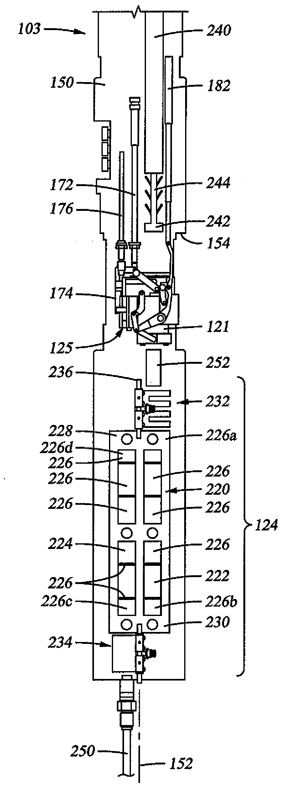
[0031]This disclosure relates to apparatus and methods for obtaining core samples from subterranean formations. In some embodiments, a sidewall coring tool includes a coring bit that is moveable between eject and coring positions using link arms. In other embodiments, the sidewall coring tool includes a storage area capable of handling and storing cores in multiple storage columns. In related embodiments, a transfer mechanism is provided for transporting the cores between the coring bit and the storage area. In still other embodiments, the sidewall coring tool may further rotate the coring bit to a sever position to assist with breaking the core sample from the formation. The apparatus and methods disclosed herein may be used in both “wireline” and “while-drilling” applications.

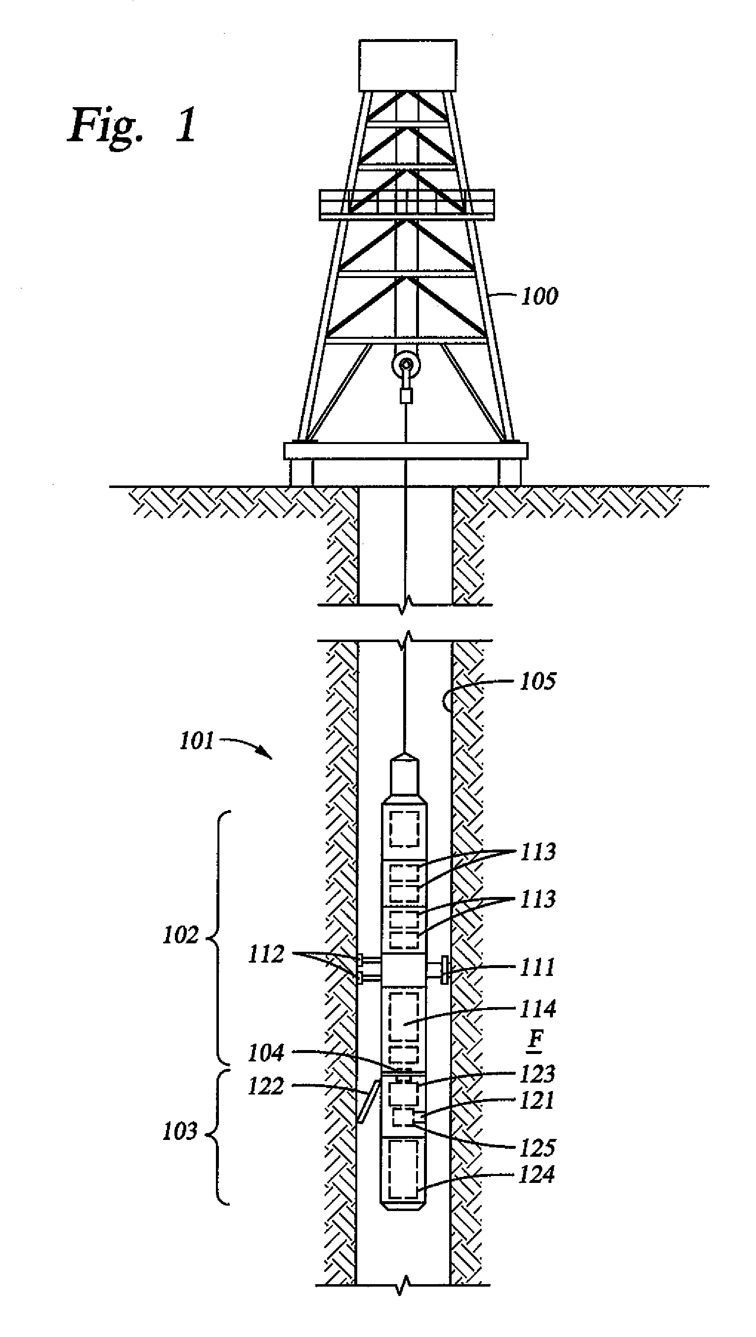
[0032]FIG. 1 shows a schematic illustration of a wireline apparatus 101 deployed into a wellbore 105 from a rig 100 in accordance with one embodiment of this disclosure. The wireline apparatus 101 includes a ...


PUM


Abstract

A coring tool for use in a borehole formed in a subterranean formation includes a tool housing with a coring aperture and a core receptacle. A coring bit is mounted within the tool housing and movable between retracted and extended positions by a series of pivotably connected extension link arms. Another set of link arms rotates the coring bit between coring and eject positions. The coring tool may also include a multi-column core storage magazine with shifters to move cores or core holders between columns. The coring tool may be used to measure core lengths during operation and facilitates retrieval of cores having larger lengths and diameters than conventional sidewall coring tools.

Description

BACKGROUND[0001]1. Technical Field[0002]This disclosure generally relates to oil and gas well drilling and the subsequent investigation of subterranean formations surrounding the well. More particularly, this disclosure relates to apparatus and methods for obtaining and handling sample cores from a subterranean formation.[0003]2. Description of the Related Art[0004]Wells are generally drilled into the ground or ocean bed to recover natural deposits of oil and gas, as well as other desirable materials that are trapped in geological formations in the Earth's crust. A well is typically drilled using a drill bit attached to the lower end of a “drill string.” Drilling fluid, or “mud,” is typically pumped down through the drill string to the drill bit. The drilling fluid lubricates and cools the drill bit, and it carries drill cuttings back to the surface in the annulus between the drill string and the wellbore wall.[0005]Once a formation of interest is reached, drillers often investigate...

Claims


Application Information

Patent Timeline
IPC IPC(8): E21B49/00
CPCE21B25/00E21B49/06
Inventor REID, JR., LENNOX ERROLLAVAURE, RACHEL AGNES
Owner SCHLUMBERGER TECH CORP
Why Eureka
Try Eureka