

Self latching latch
a self-latching, latch technology, applied in the direction of fastening means, instruments, horology, etc., can solve the problems of damage to both the tongue and/or the adjacent sash, the lock and latch mechanism is still possible to trigger or release, and the lock and latch is used on sliding windows and double hung windows
- Summary
- Abstract
- Description
- Claims
- Application Information
AI Technical Summary
Benefits of technology
Problems solved by technology
Method used
Image

Examples
Embodiment Construction
. 4-8
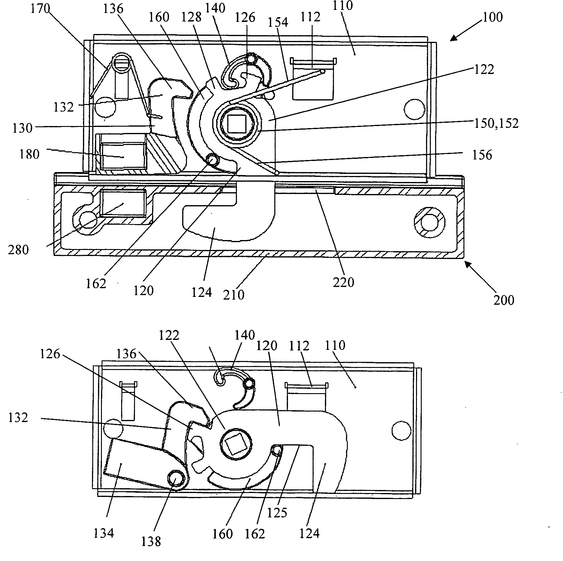
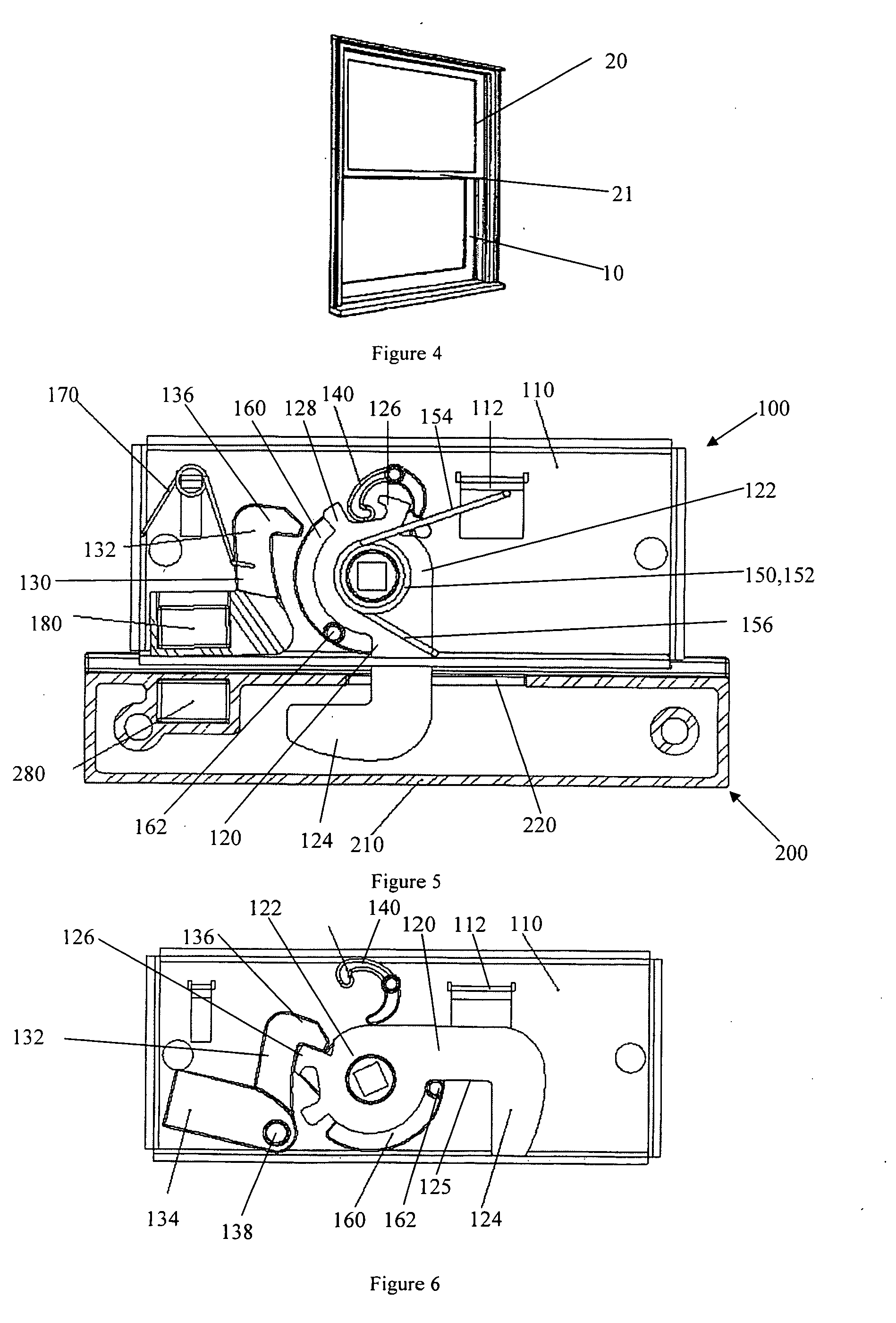
[0064]As mentioned above, the embodiment of the invention presently described is a latch mechanism for a double hung window. FIG. 4 shows a typical double hung window from the outside. The double hung window comprises a first sash 10 (which is the inner sash in this case), and a second sash 20 (which is the outer sash in this case). When the two sashes are in the closed configuration shown in FIG. 4, the lower horizontal edge 21 of the frame of second sash overlaps with the upper horizontal edge (not visible) of the frame of the first sash.
[0065]From FIG. 5 it can be seen that the latch mechanism comprises a latch 100, and a strike which will be referred to as the keeper 200. The latch 100 comprises a base 110, a latch tongue 120, a hold back member 130, a lockout cam 140, a main spring 150, a hub 160 and an auxiliary spring 170. The keeper 200 comprises a casing 210 having an opening 220 through which the latch tongue 120 can enter to hookingly-engage with the keeper, and a st...
PUM
 Abstract
Description
Claims
Application Information