Drawing device, and drawing method

a drawing device and drawing method technology, applied in the field of computer graphics, can solve the problems of more processing time, more time needed for the whole drawing time, and the total drawing time is not reduced, and achieve the effects of high computing capacity, high speed, and simplified polygon data

Inactive Publication Date: 2009-05-07
PANASONIC CORP
View PDF22 Cites 75 Cited by
  • Summary
  • Abstract
  • Description
  • Claims
  • Application Information

AI Technical Summary

Benefits of technology

[0024]With this configuration, it is possible to simplify polygon data after judging or assessing whether the process is accelerated as a whole, and can perform drawing of a three-dimensional obje

Problems solved by technology

There is a problem, however, that the processing time as the total drawing time is not reduced with the conventional method of deleting the vertices of polygons since the process of deleting the vertices of polygon takes time.
In other words, when deletion of vertices of polygon is not effective (more specifically, when the vertices

Method used


Image

  • Drawing device, and drawing method
  • Drawing device, and drawing method
  • Drawing device, and drawing method

Examples


first embodiment

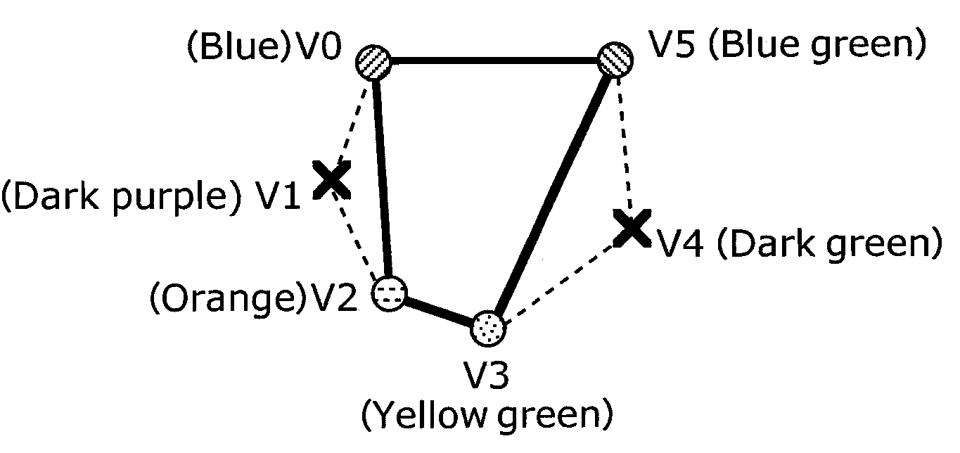
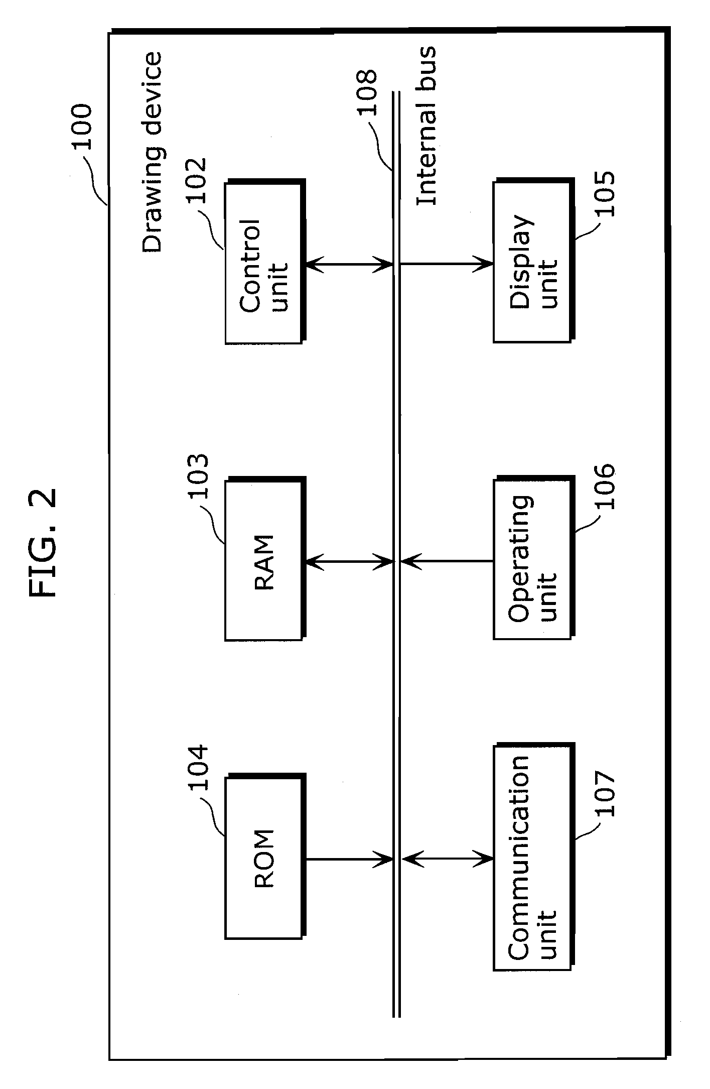
[0056]FIG. 2 is a schematic diagram showing the configuration of the drawing device 100 according to the first embodiment. The drawing device 100 according to the first embodiment simplifies polygons based on attributes in each vertex in a polygon, a three-dimensional position coordinate value, a color value attached to the vertex, a texture coordinate data, or a normal vector. The drawing method described herein is used in the drawing device 100. However, the drawing device 100 is a specific example for describing the drawing device according to the present invention. Thus, the drawing device may not be limited to the drawing device 100, and may also be other electronic devices such as mobile phones and personal computers.

[0057]As shown in FIG. 2, the drawing device 100 includes the control unit 102, the RAM 103, the ROM 104, the display unit 105, the operating unit 106 and the communication unit 107 as the major components. Note that although the drawing device 100 may also includ...

second embodiment

[0170]In the first embodiment, the embodiment in which the polygon obtained by the drawing information obtaining unit 110 is defined as the “FAN-type” is described. In the second embodiment, an embodiment in which the polygon defined as the “STRIP-type” undergoes polygon simplification process after the polygon defined as “STRIP-type” is converted to the “FAN-type” is described.

[0171]The drawing device according to the present invention is characterized in that the drawing information obtaining unit 110 in the drawing device 100 according to the first embodiment is capable of converting the polygon defined as the STRIP-type into the FAN-type. Other functions are the same as the drawing device 100 according to the first embodiment.

[0172]FIG. 14 is a figure showing two forms of polygons when defining a polygon (hexagon in FIG. 14). As shown in FIG. 14, the polygon defined as the STRIP-type (STRIP-type polygon) is defined in a top-down zigzag form (for example, along with the y-coordin...


PUM


Abstract

A device that is not necessarily high in performance, includes: a standard information obtaining unit configured to obtain standard information including a type of drawing process that could be used for computer graphics and a feature of the shape of polygon; a drawing information obtaining unit configured to obtain drawing information including information indicating the type of drawing process used for the actual computer graphics and information indicating the shape of polygon; a simplification judging unit configured to judge whether the type of the drawing process and the shape of the polygon indicated by the drawing information satisfy the standard indicated by the drawing standard information; a polygon simplifying unit configured to simplify the polygon by reducing vertices composing the polygon when said simplification judging unit judges that the standard is satisfied; and a drawing unit configured to execute computer graphics process using the polygon whose vertices are reduced, in order to achieve simplification of polygons and reduction of the total processing time for computer graphics (CG).

Description

TECHNICAL FIELD[0001]The present invention relates to computer graphics on computers, information devices, mobile phones and gaming machines, and particularly relates to an approximation technique for curved surface and curved lines.BACKGROUND ART[0002]In three-dimensional computer graphics, three-dimensional curved surfaces are drawn by approximating the curved surfaces with polygons.[0003]Since drawing using polygons requires enormous amount of processing time, a conventional technique for simplifying the drawing process by reducing the number of vertices of polygon has been proposed (see Patent Reference 1, for example).[0004]FIG. 1 is a block diagram of the conventional textured data generating device. The conventional textured data generating device reduces the number of polygons by a polygon reducing unit 1. The vertex position calculating unit 2 calculates a corresponding position of the vertices deleted by the polygon reducing unit 1 in a new triangle patch, and stores the b...

Claims


Application Information

Patent Timeline
IPC IPC(8): G06T11/20G09G5/00G06T15/00
CPCG06T17/20G06T15/00
Inventor SHIMASAKI, TAKAMASAFUKAMI, YUKIYASUSIRAI, YASUHISA
Owner PANASONIC CORP
Why Eureka
Try Eureka