Rotary-actuated medical puncturing device

a technology of rotary action and puncturing device, which is applied in the direction of manufacturing tools, catheters, diagnostic recording/measuring, etc., can solve the problems of difficult physical and psychologically for many people to prick their own finger with a hand-held needle or blade, and achieve the effects of simple, reliable, and reliabl

Active Publication Date: 2009-05-07
BECTON DICKINSON & CO
View PDF15 Cites 18 Cited by
  • Summary
  • Abstract
  • Description
  • Claims
  • Application Information

AI Technical Summary

Benefits of technology

[0015]In still another embodiment of the invention, a medical puncturing device is provided comprising an actuator and a shield, the shield and the actuator movably associated with each other. The medical puncturing device further includes a skin puncturing assembly disposed at least partially within the shield, the skin puncturing assembly comprising a carrier and a skin puncturing element mounted to the carrier, and the carrier movable from a first position to a second position. When the carrier is in the first position, the shield has a shield interference surface engageable with a carrier interference surface of the carrier. In addition, when a force is applied to the actuator, the carrier is capable of rotation which enables disengagement of the shield interference surface from the carrier interference surface, thereby causing the carrier to move from the first position to the second position.

Problems solved by technology

It is often physiologically and psychologically difficult for many people to prick their own finger with a hand-held needle or blade.

Method used


Image

  • Rotary-actuated medical puncturing device
  • Rotary-actuated medical puncturing device
  • Rotary-actuated medical puncturing device

Examples


Embodiment Construction

[0035]For purposes of the description hereinafter, the terms “upper”, “lower”, “right”, “left”, “vertical”, “horizontal”, “top”, “bottom”, and derivatives thereof shall relate to embodiments of the invention, as it is oriented in the drawing figures. However, it is to be understood that embodiments of the invention may include many alternative variations and step sequences except where expressly specified to the contrary. It is also to be understood that the specific devices and processes illustrated in the attached drawings and described in the following text are simply exemplary embodiments of the invention. Hence, specific dimensions and other physical characteristics related to the embodiments disclosed hereinafter are not to be considered limiting.

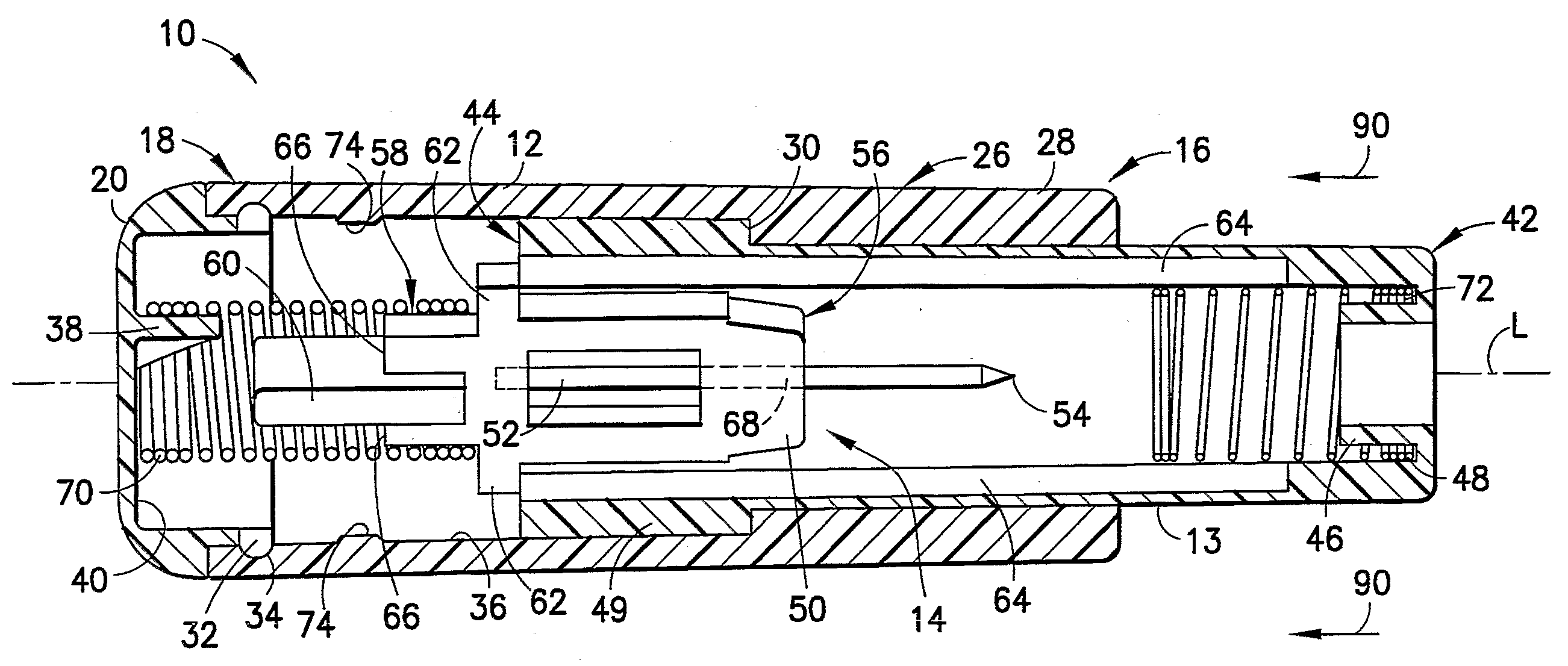
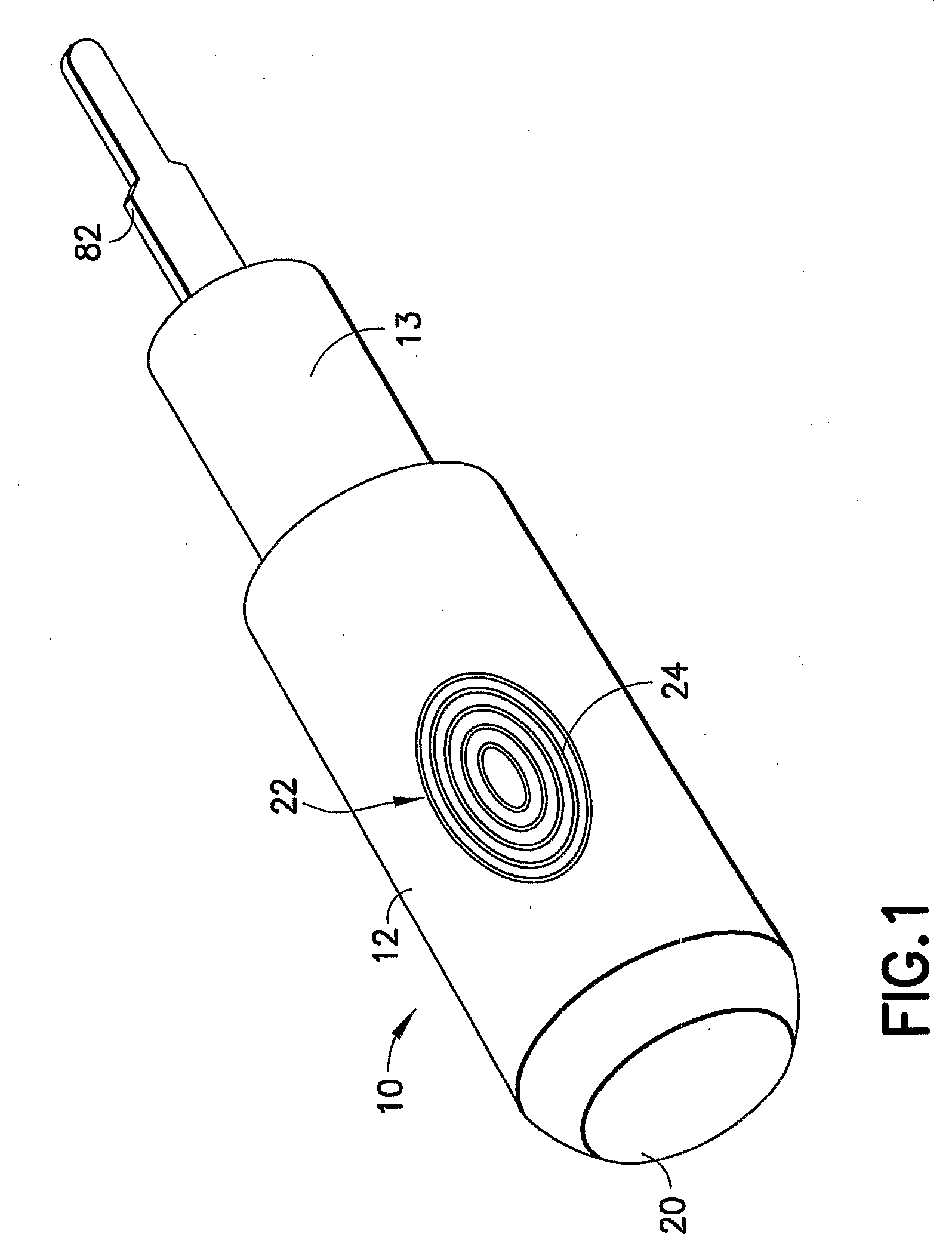
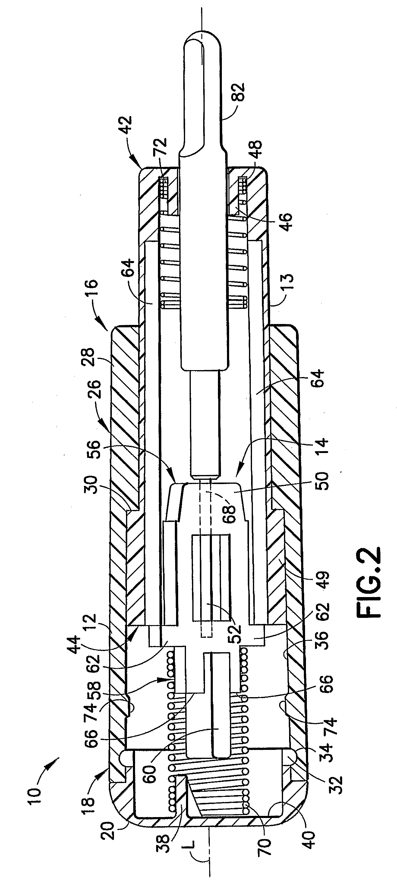
[0036]Referring to FIGS. 1-5, a medical puncturing device or lancet 10 (hereinafter “puncturing device 10”) in accordance with an embodiment of the present invention is generally illustrated. The puncturing device 10 generally include...


PUM

PropertyMeasurementUnit
forceaaaaaaaaaa
relative movementaaaaaaaaaa
disease transmissionaaaaaaaaaa

Abstract

The medical puncturing device includes an actuator, a shield, and a skin puncturing assembly. The actuator and shield are movable relative to one another. The skin puncturing assembly includes a carrier and a skin puncturing element. A distal end of the skin puncturing element is adapted for puncturing the skin of a patient. The carrier is movable from a retracted position wherein the distal end of the skin puncturing element is disposed within the shield to a puncturing position wherein the distal end of the skin puncturing element is exposed to puncture the skin of a patient. The carrier is maintained in the retracted position by interference engagement between the carrier and shield. A drive spring is provided to move the carrier from the retracted to puncturing positions. A retraction spring is provided to return the carrier to a position wherein the shield encompasses the skin puncturing element.

Description

[0001]The present application claims the benefit of U.S. Provisional Application No. 60 / 569,479, filed on May 7, 2004, under 35 U.S.C. 119(e).BACKGROUND OF THE INVENTION[0002]1. Field of the Invention[0003]present invention relates generally to medical puncturing devices, commonly referred to as lancets, used to take blood samples from patients and, more specifically, to a medical puncturing device that ensures sterility before use and safe and secure disposal after use.[0004]2. Description of Related Art[0005]Medical puncturing devices are used in the medical field for puncturing the skin of a patient to obtain a capillary blood sample from the patient. Certain diseases, such as diabetes, require that the patient's blood be tested on a regular basis to monitor, for example, the patient's blood sugar levels. Additionally, test kits, such as cholesterol test kits, often require a blood sample for analysis. The blood collection procedure usually involves pricking a finger or other sui...

Claims


Application Information

Patent Timeline
Patent Type & Authority Applications(United States)
IPC IPC(8): A61B17/32B23P11/00A61B5/15
CPCY10T29/49826A61B5/1411A61B5/150022A61B5/150259A61B5/150412A61B5/150442A61B5/150503A61B5/150564A61B5/150618A61B5/150717A61B5/150885A61B5/15111A61B5/15117A61B5/1513A61B5/15144A61B5/150832A61B5/1405
Inventor DICESARE, PAULBATTLES, CHRISTOPHERRADZIUNAS, JEFFREY
Owner BECTON DICKINSON & CO
Why Eureka
Try Eureka