Band pass filter with tunable phase cancellation circuit

a phase cancellation circuit and filter technology, applied in the field of filters, can solve the problems of requiring a substantial amount of additional space for installing cavity filters, requiring additional isolation at specific frequencies, and affecting the operation of communication equipment,

Inactive Publication Date: 2009-05-14
COMPROD COMM
View PDF1 Cites 39 Cited by
  • Summary
  • Abstract
  • Description
  • Claims
  • Application Information

AI Technical Summary

Benefits of technology

[0014]These and other objects and advantages of the present invention will be readily appreciable from the f

Problems solved by technology

However, communications equipment, receivers particularly, may require additional isolation at specific frequencies.
However, this is not always ideal as it requires multiple fil

Method used


Image

  • Band pass filter with tunable phase cancellation circuit
  • Band pass filter with tunable phase cancellation circuit
  • Band pass filter with tunable phase cancellation circuit

Examples


Embodiment Construction

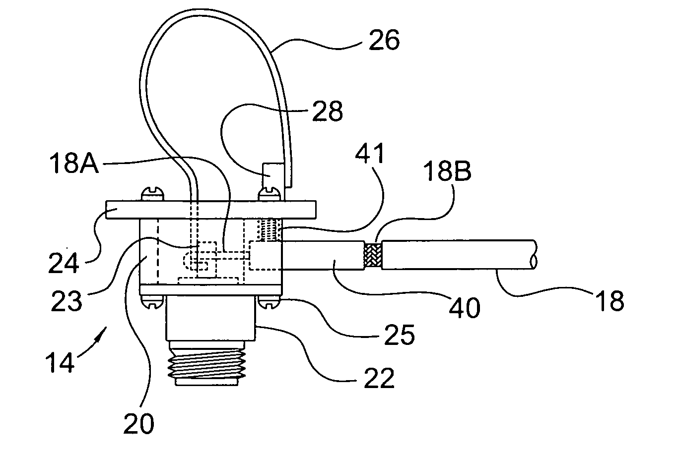
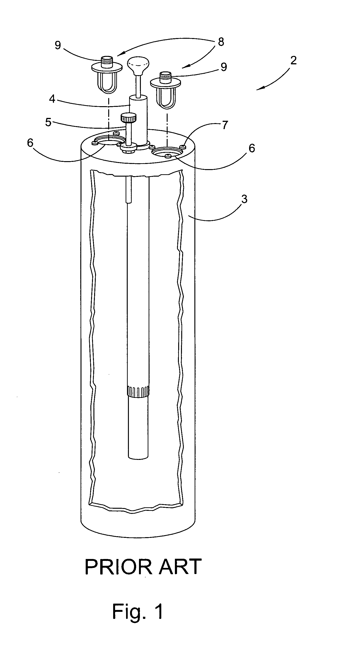
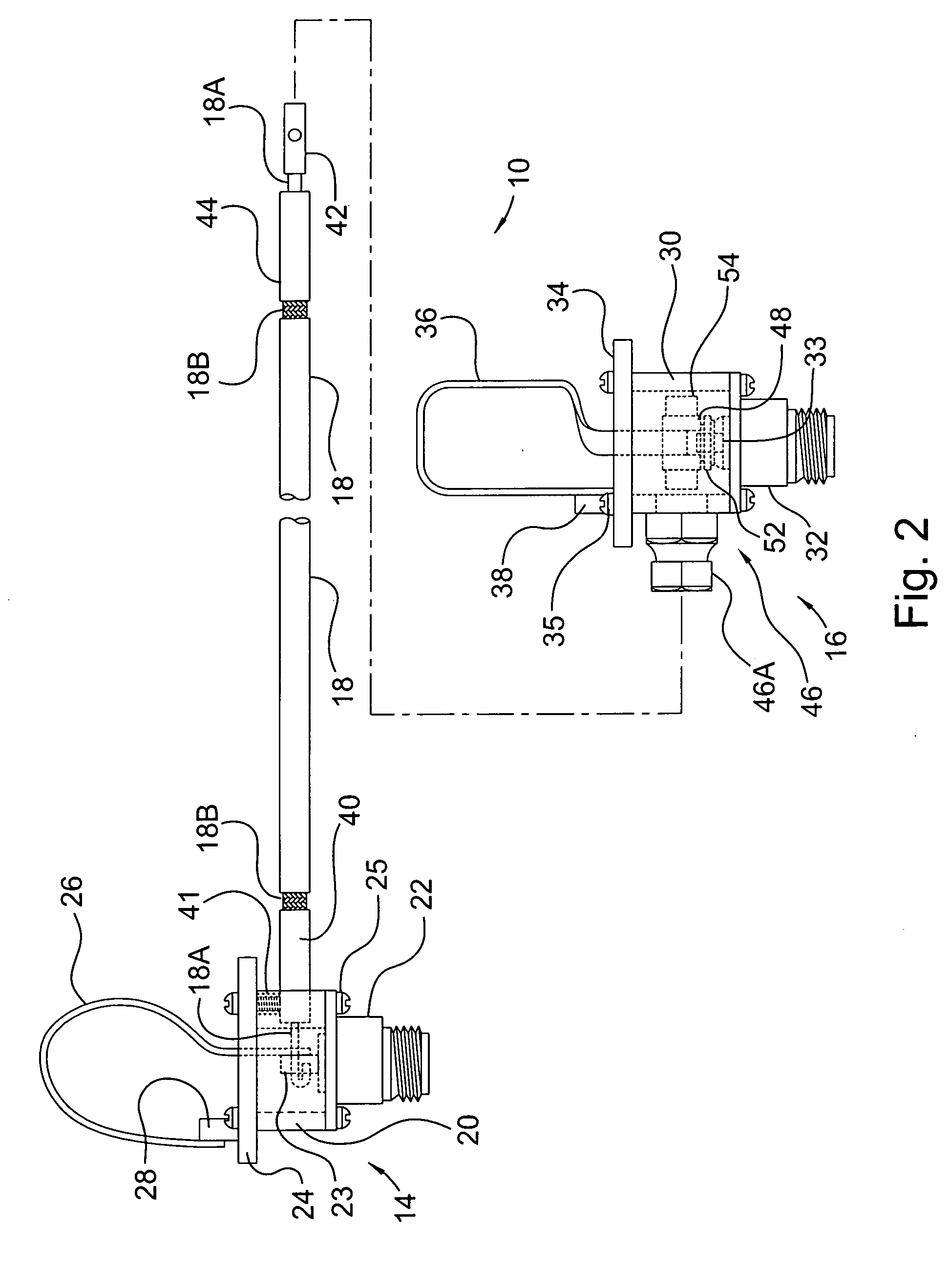
[0022]At the outset, it should be appreciated that like drawing numbers on different drawing views identify identical, or functionally similar, structural elements of the invention. While the present invention is described with respect to what is presently considered to be the preferred aspects, it is to be understood that the invention as claimed is not limited to the disclosed aspects. Also, the adjectives, “top,”“bottom,”“right,”“left,” and their derivatives, in the description herebelow, refer to the perspective of one facing the invention as shown in the figure under discussion.

[0023]Furthermore, it should be understood that this invention is not limited to the particular methodology, materials and modifications described and as such may, of course, vary. It should also be understood that the terminology used herein is for the purpose of describing particular aspects only, and is not intended to limit the scope of the present invention, which is limited only by the appended cla...


PUM


Abstract

A phase cancellation circuit for a cavity filter including a sampler loop assembly arranged to receive an input signal, a variable loop assembly connected to the sampler loop assembly by a cable, wherein the variable loop assembly is arranged to transmit an output signal from cavity filter, wherein the sampler loop assembly samples a cancellation signal at an isolation frequency from the input signal and transmits the cancellation signal to the variable loop assembly via the cable, and, wherein the cable has a length equal to a multiple of a half-wavelength at the desired isolation frequency, wherein the cancellation signal undergoes a 180° phase shift by traveling through the cable, wherein the variable loop assembly combines the cancellation signal with the input signal to cancel the input signal at the isolation frequency due to the 180° phase shift for creating the output signal with a notch at the isolation frequency.

Description

CROSS REFERENCE TO RELATED APPLICATIONS[0001]This patent application claims the benefit under 35 U.S.C. §119(e) of U.S. Provisional Application No. 61 / 003,024, filed Nov. 14, 2007, which application is incorporated herein by reference.FIELD OF THE INVENTION[0002]This invention relates to filters used in the field of RF communication, more specifically to cavity filters, and even more specifically to phase cancellation circuits for bandpass cavity filters.BACKGROUND OF THE INVENTION[0003]A band pass cavity filter preferably passes one narrow band of frequencies and attenuates all others with increasing attenuation above and below the pass frequency. Band pass filters are ideal when the interfering frequencies are not known to any degree of accuracy or when very broadband filtering is needed. Collectively, the frequencies that are allowed to pass are called the pass band.[0004]Bandpass filters are well known in the art. An example of a bandpass cavity filter is shown in FIG. 1. Cavity...

Claims


Application Information

Patent Timeline
IPC IPC(8): G01S3/16
CPCH01P1/208
Inventor KAEGEBEIN, DANIEL P.
Owner COMPROD COMM
Why Eureka
Try Eureka