

Communication apparatus, communication method, antenna module and communication system
a communication system and communication apparatus technology, applied in the field of communication apparatus, communication method, antenna module and communication system, can solve the problems of difficult to sufficiently lengthen the distance between the antennas, difficult to reduce the interference caused by this coupling, and difficulty in reducing the interference caused by the communication system. , to achieve the effect of reducing the interference caused by the communication system
- Summary
- Abstract
- Description
- Claims
- Application Information
AI Technical Summary
Benefits of technology
Problems solved by technology
Method used
Image

Examples
first embodiment
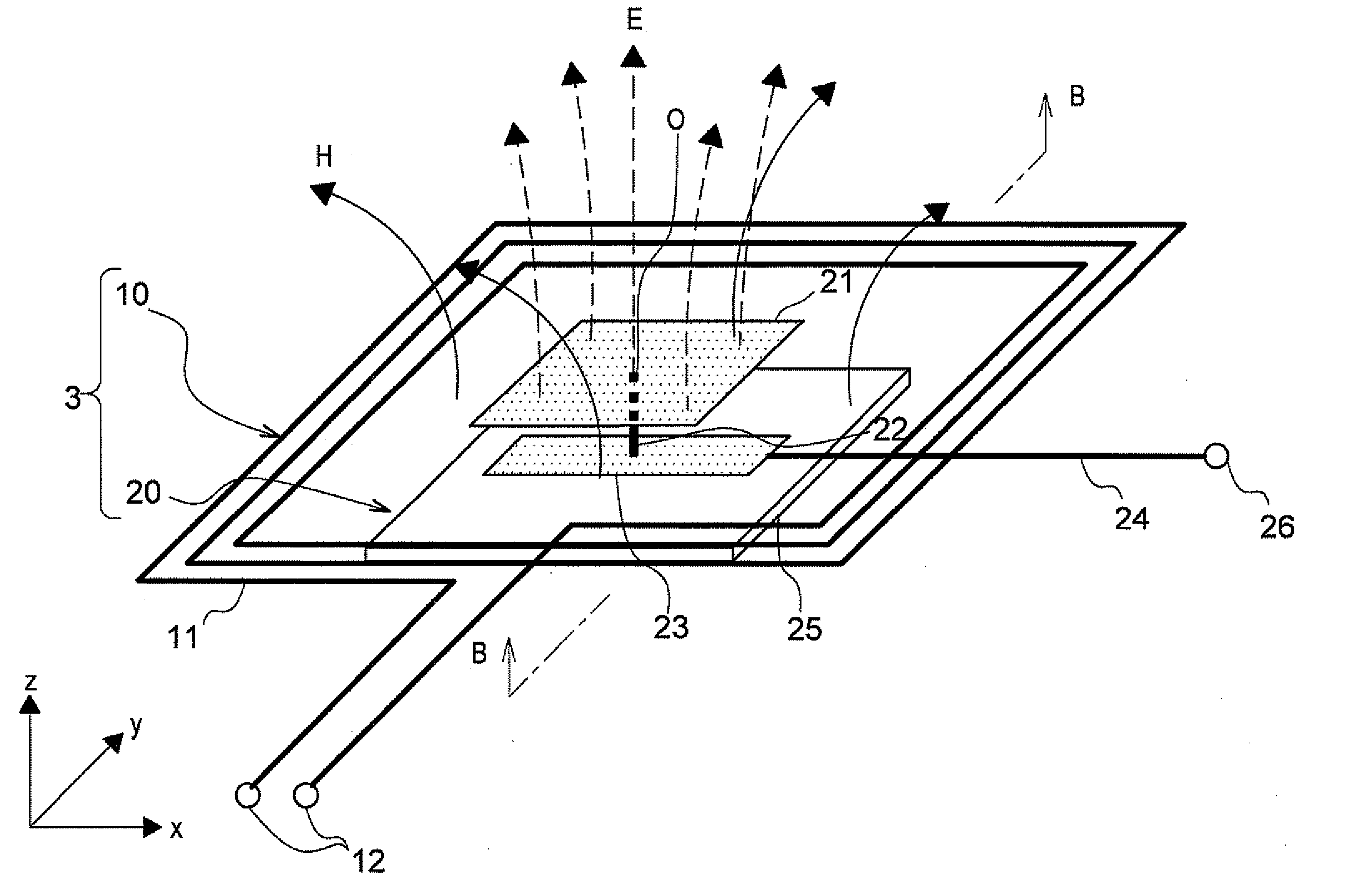
[0056]A constitution of the communication apparatus according to a first embodiment of the present invention is described with reference to FIGS. 1 and 2.
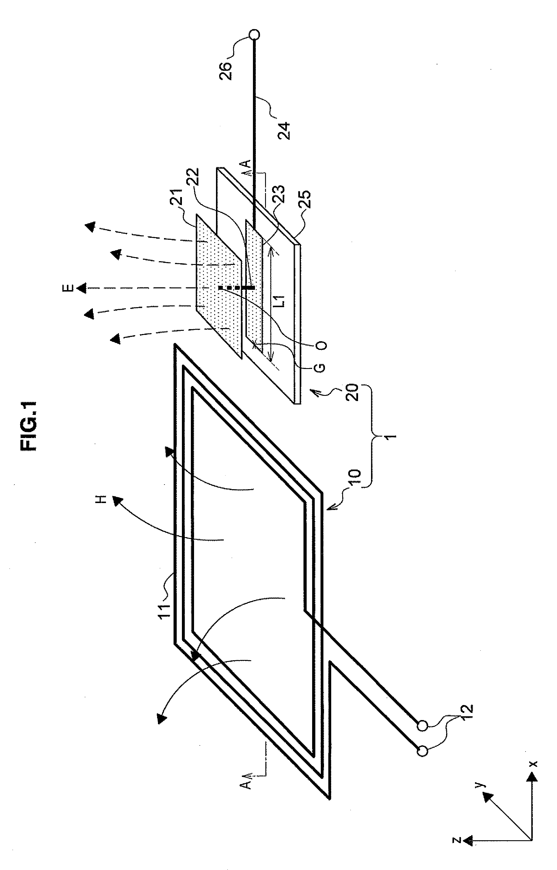
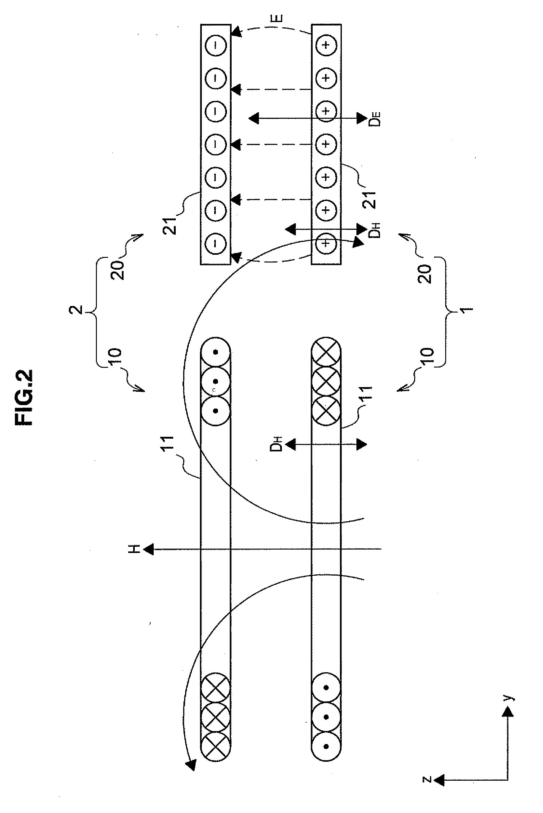
[0057]FIG. 1 is an explanatory diagram illustrating the constitution of the communication apparatus according to the first embodiment. FIG. 2 is a schematic cross-sectional view taken along line A-A of FIG. 1, and is an explanatory diagram illustrating a constitution that one communication apparatus makes contactless communication with the other communication apparatus according to the first embodiment. The communication apparatus 1 is on the transmission side, and the communication apparatus 2 is on the reception side. FIG. 1 illustrates the communication apparatus 1 on the transmission side, and the communication apparatus 1 on the transmission side is mainly described below, but the communication apparatus 2 on the reception side can be constituted similarly to the communication apparatus 1 on the transmission side as shown in F...
second embodiment
[0098]FIG. 6 is an explanatory diagram illustrating a constitution of the communication apparatus according to the second embodiment of the present invention. FIG. 7 is a schematic cross-sectional view taken along line B-B of FIG. 6 and is an explanatory diagram illustrating a constitution where contactless communication is made between one communication apparatus and the other communication apparatus according to the second embodiment. In the second embodiment, a communication apparatus 3 is on the transmission side, and a communication apparatus 4 is on the reception side. FIG. 6 illustrates the communication apparatus 3 on the transmission side, and it is described mainly, but the communication apparatus 4 on the reception side and the communication apparatus 3 on the transmission side can be constituted similarly as shown in FIG. 7. The communication apparatus 4 on the reception side can transmit data, and the communication apparatus 3 on the transmission side can receive data.
[...
third embodiment
[0109]FIG. 9 is an explanatory diagram illustrating a constitution of the communication apparatus according to the third embodiment. The communication apparatus 5 according to the third embodiment has a coupling electrode 51 instead of the coupling electrode 21 of the communication apparatus 3 according to the second embodiment. Since the other parts of the constitution of the communication apparatus 5 according to the third embodiment are similar to those of the communication apparatus 3 according to the second embodiment, the detailed description thereof is omitted.
[0110]The coupling electrode 51 of the communication apparatus 5 according to the third embodiment is arranged similarly to the coupling electrode 21 in the first and second embodiments. Therefore, the coupling electrode 51 can couple electric fields efficiently via the electric field E.
[0111]The coupling electrode 51 of the communication apparatus 5 according to the third embodiment has a plurality of slits 52 which is...
PUM
 Abstract
Description
Claims
Application Information