
Analytical instrument and analysis system

an analytical instrument and analysis system technology, applied in the field of analytical instruments and analysis systems, can solve the problems of affecting the arrangement of an additional auto injector or an auto sampler

Pending Publication Date: 2022-05-12
SHIMADZU CORP
View PDF5 Cites 0 Cited by
  • Summary
  • Abstract
  • Description
  • Claims
  • Application Information

AI Technical Summary

Benefits of technology

The present invention aims to reduce interference caused by cables connected to analytical instruments. The analytical instrument has multiple connection ports for cables, which can be connected to the instrument's electrical circuit. By selecting the connection position of the cable, the risk of interference is minimized. This results in a cable that is less likely to interfere with the user's work or other devices.

Problems solved by technology

For this reason, depending on an arrangement direction of an auto injector, there may occur a problem that a cable connected to the auto injector protrudes to the front or the side of the analysis system and becomes an obstacle when the user works or interferes with other optional devices.
Also in such a case, there may occur a problem that a cable connected to the auto injector hinders arrangement of an additional auto injector or an auto sampler.

Method used


Image

  • Analytical instrument and analysis system
  • Analytical instrument and analysis system
  • Analytical instrument and analysis system

Examples


Embodiment Construction

[0015]Hereinafter, an embodiment of an analytical instrument according to the present invention and an embodiment of an analysis system including the analytical instrument will be described with reference to the drawings.

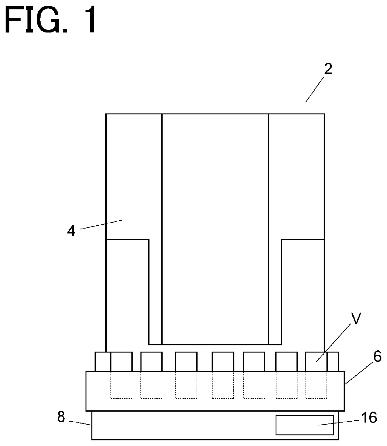
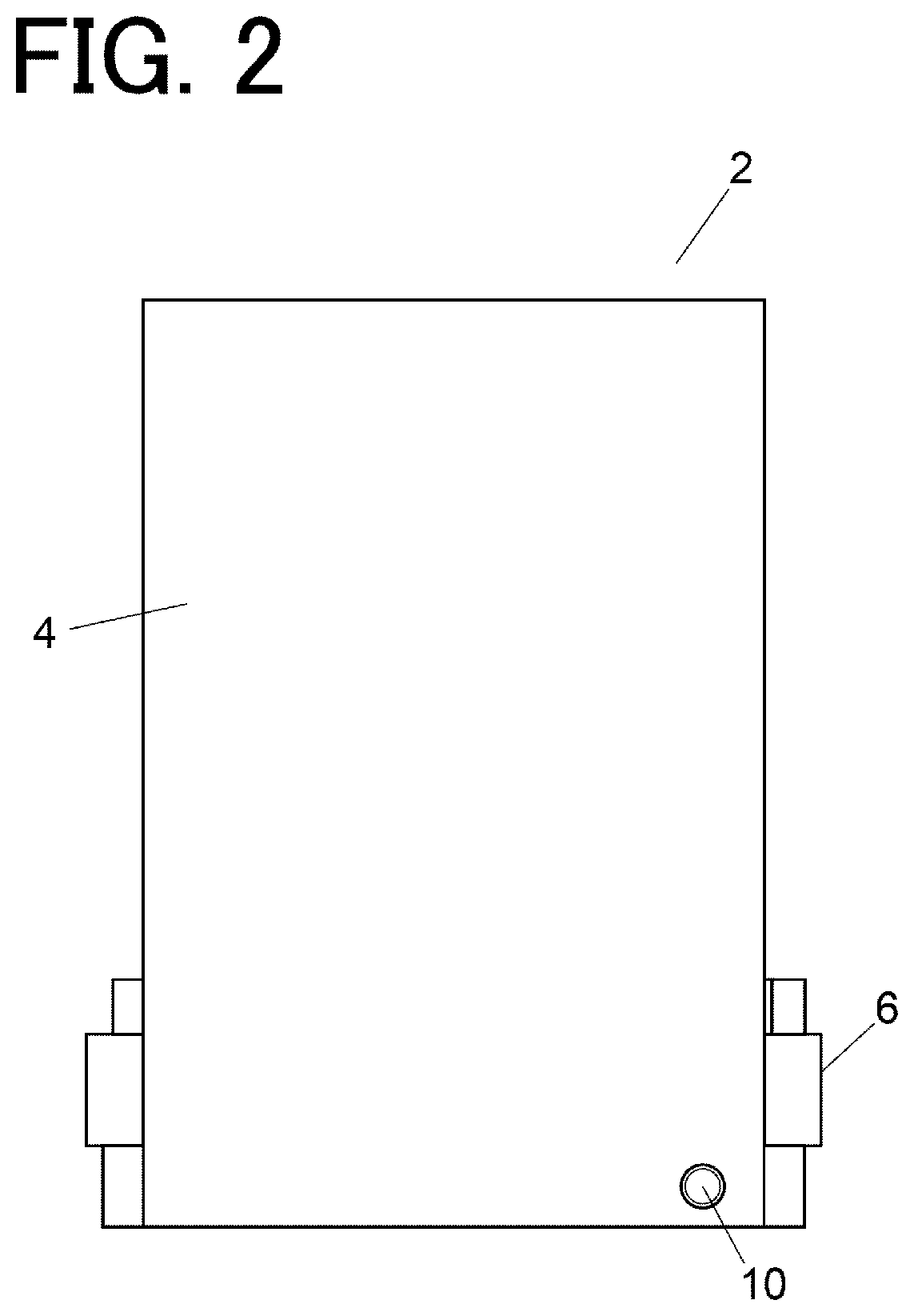
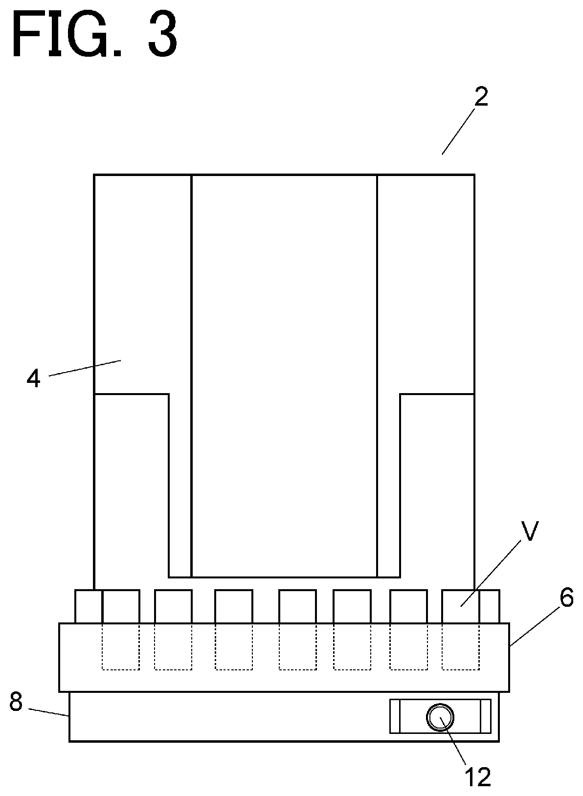
[0016]An embodiment of the analytical instrument will be described with reference to FIGS. 1 to 3. FIGS. 1 and 3 are front views, and FIG. 2 is a rear view. Here, an auto injector for gas chromatography analysis will be described as an example of the analytical instrument.

[0017]The auto injector 2 includes an injector main body 4, a turret 6, and a base 8. The injector main body 4 and the base 8 are integrated.

[0018]The turret 6 is a circular table that rotates in a horizontal plane on the base 8. In the turret 6, a plurality of vials V containing liquid such as a sample and a solvent are set on the same circumference, and each of the vials V is conveyed along a circular track as the turret 6 rotates. The base 8 includes a turret drive mechanism (not shown) for rota...


PUM


Abstract

To make a cable connected to an analytical instrument less likely to cause interference. An analytical instrument (2) includes an executing part (18) configured to execute an operation related to an analysis, and an electrical circuit (20) electrically connected to the executing part (18). The analytical instrument (2) constitutes an analysis system (1) together with an analysis device (100). A plurality of connection ports (10; 12) configured to receive a cable (200; 300) coming from outside of the analytical instrument (1) are provided at different positions in a manner that directions for receiving the cable (200; 300) are different from each other. The analytical instrument (1) is configured to connect electrically the electrical circuit (20) with the cable (200; 300) connected to a connection port which is optionally selected among the plurality of connection ports (10; 12).

Description

BACKGROUND OF THE INVENTION1. Field of the Invention[0001]The present invention relates to an analytical instrument and an analysis system.2. Description of the Related Art[0002]An analysis system such as a gas chromatography analysis system is constructed by combining an analytical instrument such as an auto injector with a gas chromatograph (analysis device). An auto injector is a device that is arranged on a gas chromatograph and automatically injects a sample into a sample vaporizing chamber of the gas chromatograph. An analytical instrument such as an auto injector needs to receive power supply and synchronize operation with a gas chromatograph or other devices, and is electrically connected to a gas chromatograph or the like via a cable.SUMMARY OF THE INVENTION[0003]An analytical instrument, such as an auto injector, may be arranged on a gas chromatograph in various orientations. For this reason, depending on an arrangement direction of an auto injector, there may occur a prob...

Claims


Application Information

Patent Timeline
IPC IPC(8): G01N30/24
CPCG01N30/24G01N2030/025G01N30/02G01N30/88
Inventor OKADA, MASAYUKIKOJIMA, MASAHIRO
Owner SHIMADZU CORP
Learn More