Nozzle unit for applying damping material, and damping material application apparatus

a technology of damping material and nozzle unit, which is applied in the direction of spray nozzles, spraying apparatus, coatings, etc., can solve the problems of difficult to apply damping material, easy interference of motors with work pieces, and work pieces, and achieves easy regulation of the slit width of the discharge port. , the effect of easy interference with work pieces

Active Publication Date: 2014-08-26
TOYOTA JIDOSHA KK
View PDF23 Cites 0 Cited by
  • Summary
  • Abstract
  • Description
  • Claims
  • Application Information

AI Technical Summary

Benefits of technology

[0008]A first aspect of the invention relates to a nozzle unit for applying damping material onto a work piece. The nozzle unit includes: a nozzle that has a discharge port, which has a slit shape, and that discharges the damping material from the discharge port; a motor that is fixed to the nozzle; and a slit width changing device that changes the slit width of the discharge port using rotation of the motor. In this way, the slit width of the discharge port is controlled by the motor, so it is possible to easily regulate the slit width of the discharge port through a program, or the like.
[0010]In the above configuration, the nozzle unit may further include a rotation transmitting device, the motor may be arranged in such an orientation that a first rotary shaft of the motor is aligned in a direction in which the damping material is discharged from the nozzle, the rotation transmitting device may transmit rotation of the first rotary shaft to a second rotary shaft that extends toward the nozzle, and the slit width changing device may change the slit width of the discharge port in accordance with rotation of the second rotary shaft. In this nozzle unit, the motor is fixed to the nozzle in such an orientation that the first rotary shaft of the motor extends in a direction in which the damping material is discharged. The size of the motor in the direction perpendicular to the first rotary shaft is not so large. Thus, the motor is fixed to the nozzle in this way, so the motor does not extremely protrude from the side face of the nozzle. Therefore, when the damping material is applied, it is less likely that the motor interferes with the work piece. In addition, rotation of the first rotary shaft of the motor is transmitted to the second rotary shaft, extending toward the nozzle, via the rotation transmitting device. The slit width changing device changes the slit width of the discharge port using rotation of the second rotary shaft. Therefore, by controlling the motor, the slit width of the discharge port of the nozzle may be controlled.
[0011]In the above configuration, the rotation transmitting device may transmit rotation of the first rotary shaft to the second rotary shaft so that the rotational speed of the second rotary shaft is lower than the rotational speed of the first rotary shaft of the motor. With the above configuration, the rotation angle of the second rotary shaft may be smaller than the rotation angle of the rotary shaft of the motor, so it is possible to further minutely regulate the slit width of the discharge port of the nozzle when the operation of the motor is controlled.
[0013]The above described damping material application apparatus may further include a thickness measuring device that measures the thickness of the applied damping material, wherein, during application of the damping material, the controller may change at least one of the control target value of the slit width of the discharge port of the nozzle, the control target value of the discharge speed of the damping material and the control target value of the relative travel speed between the nozzle and the work piece in the direction of the slit width of the nozzle on the basis of a difference between the target thickness and the thickness measured by the thickness measuring device. With the above configuration, the thickness of the damping material may be further accurately controlled.

Problems solved by technology

Therefore, if the motor is secured to the nozzle, there is a possibility that the motor interferes with the work piece and then it is difficult to apply the damping material.
Therefore, the motor easily interferes with the work piece, and an area in which the damping material may be applied is reduced.

Method used


Image

  • Nozzle unit for applying damping material, and damping material application apparatus
  • Nozzle unit for applying damping material, and damping material application apparatus
  • Nozzle unit for applying damping material, and damping material application apparatus

Examples


Embodiment Construction

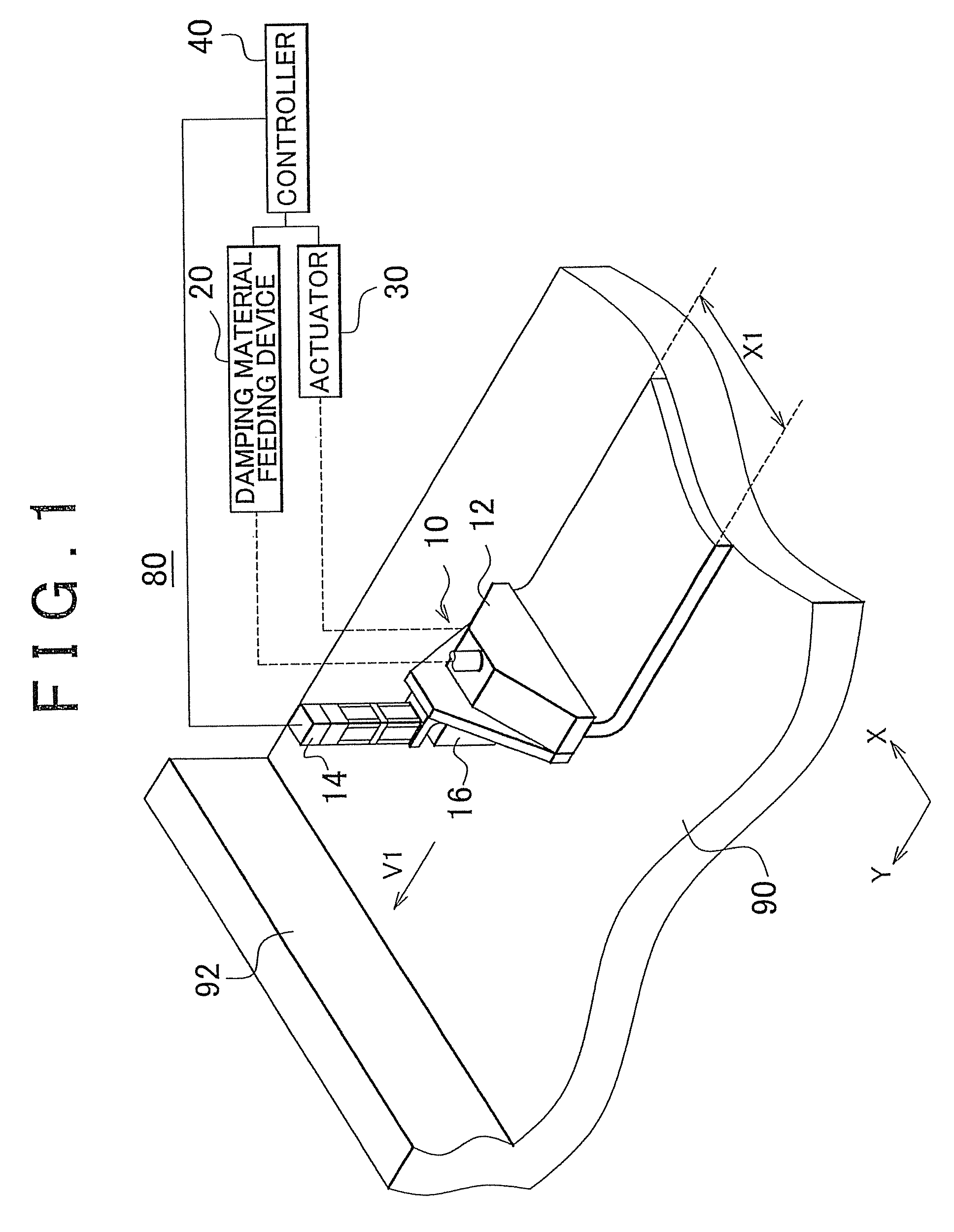
[0031]A damping material application apparatus according to an embodiment of the invention will be described. FIG. 1 shows a state where damping material is applied onto a work piece 90 by a damping material application apparatus 80 according to the embodiment. As shown in the drawing, the damping material application apparatus 80 includes a nozzle unit 10, a damping material feeding device 20, an actuator 30 and a controller 40.

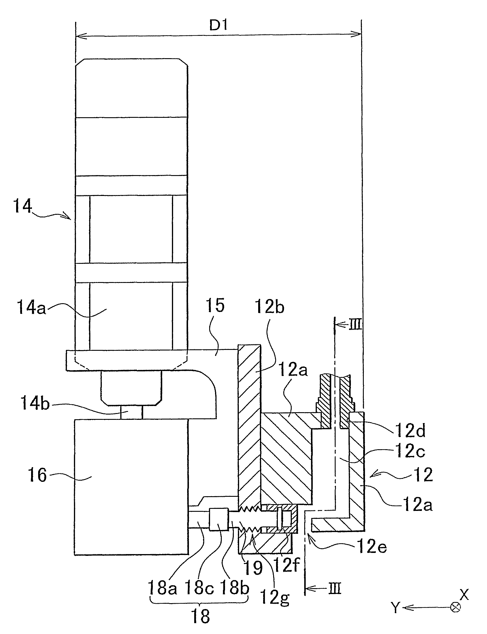
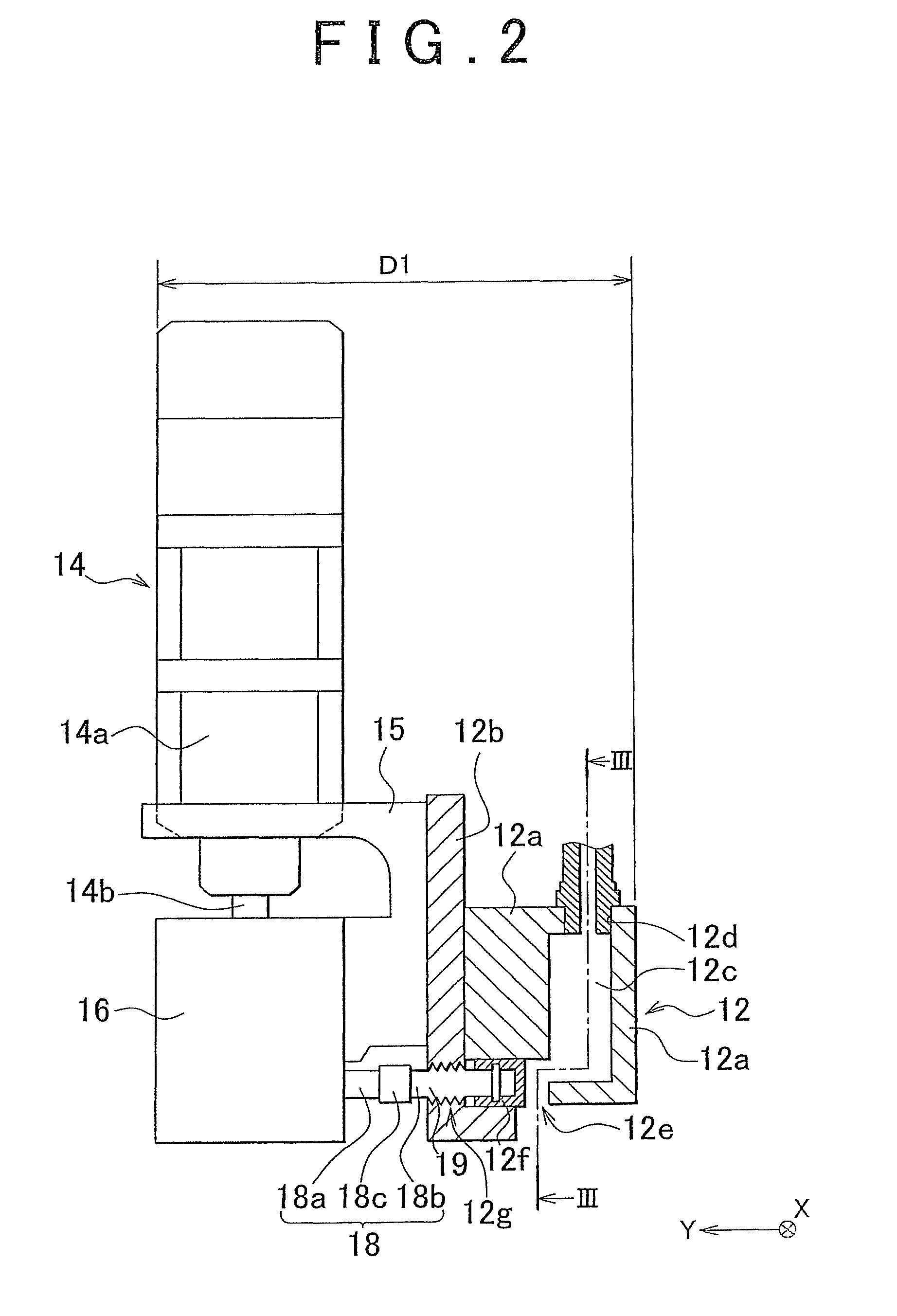
[0032]FIG. 2 shows the nozzle unit 10 as viewed in the X direction in FIG. 1. As shown in FIG. 2, the nozzle unit 10 includes a nozzle 12, a servo motor 14 and a gear box 16. FIG. 2 shows the cross-sectional view of the nozzle 12. FIG. 3 shows a longitudinal cross-sectional view of the nozzle 12, taken along the line III-III in FIG. 2, as viewed in plan view in a direction indicated by the arrows. FIG. 4 shows a plan view of the nozzle 12 as viewed from the bottom side.

[0033]As shown in FIG. 2 to FIG. 4, the nozzle 12 is formed of a case 12a and a case 12b t...


PUM


Abstract

A nozzle unit for applying damping material onto a work piece includes a nozzle that has a slit-like discharge port and that discharges the damping material from the discharge port; a motor that is fixed to the nozzle; and a slit width changing device that changes the slit width of the discharge port using rotation of the motor.

Description

[0001]This is a 371 national phase application of PCT / IB2010 / 001305 filed 20 May 2010, claiming priority to Japanese Patent Application No. 2009-127227 filed 27 May 2009, the contents of which are incorporated herein by reference.BACKGROUND OF THE INVENTION[0002]1. Field of the Invention[0003]The invention relates to a nozzle unit for applying damping material, and a damping material application apparatus.[0004]2. Description of the Related Art[0005]There is known a technique for forming a damping material layer on the surface of a structure that requires vibration damping property. For example, Japanese Patent Application Publication No. 2009-6302 (JP-A-2009-6302) describes that a damping material layer is faulted on a floor panel of an automobile to thereby improve the vibration damping property inside a vehicle cabin. To form the damping material layer, uncured damping material is applied to the surface of a work piece on which a damping material layer is formed. Then, the applie...

Claims


Application Information

Patent Timeline
Patent Type & Authority Patents(United States)
IPC IPC(8): B05B1/26
CPCB05C5/0262B05C11/1005
Inventor IWANO, YOSHIHIROMIYAGAWA, TOSHIFUMI
Owner TOYOTA JIDOSHA KK
Why Eureka
Try Eureka