Tail gas collecting equipment for automotive fault overhauling

A technology for exhaust gas collection and car failure, applied in gas treatment, cleaning methods and appliances, sound-generating devices, etc., can solve problems such as complicated operation process and poor exhaust gas collection effect, and achieve the effect of reducing damage and eliminating noise

Active Publication Date: 2019-01-04
付安英
View PDF6 Cites 0 Cited by
  • Summary
  • Abstract
  • Description
  • Claims
  • Application Information

AI Technical Summary

Problems solved by technology

[0003] In order to overcome the disadvantages of complex operation process and poor exhaust gas collection effect of traditional exhaust gas collection equipment, the technical problem to be solved is to provide an exhaust gas collection equipment for automobile troubleshooting with convenient operation and good exhaust gas collection effect

Method used


Image

  • Tail gas collecting equipment for automotive fault overhauling
  • Tail gas collecting equipment for automotive fault overhauling
  • Tail gas collecting equipment for automotive fault overhauling

Examples


Embodiment 1

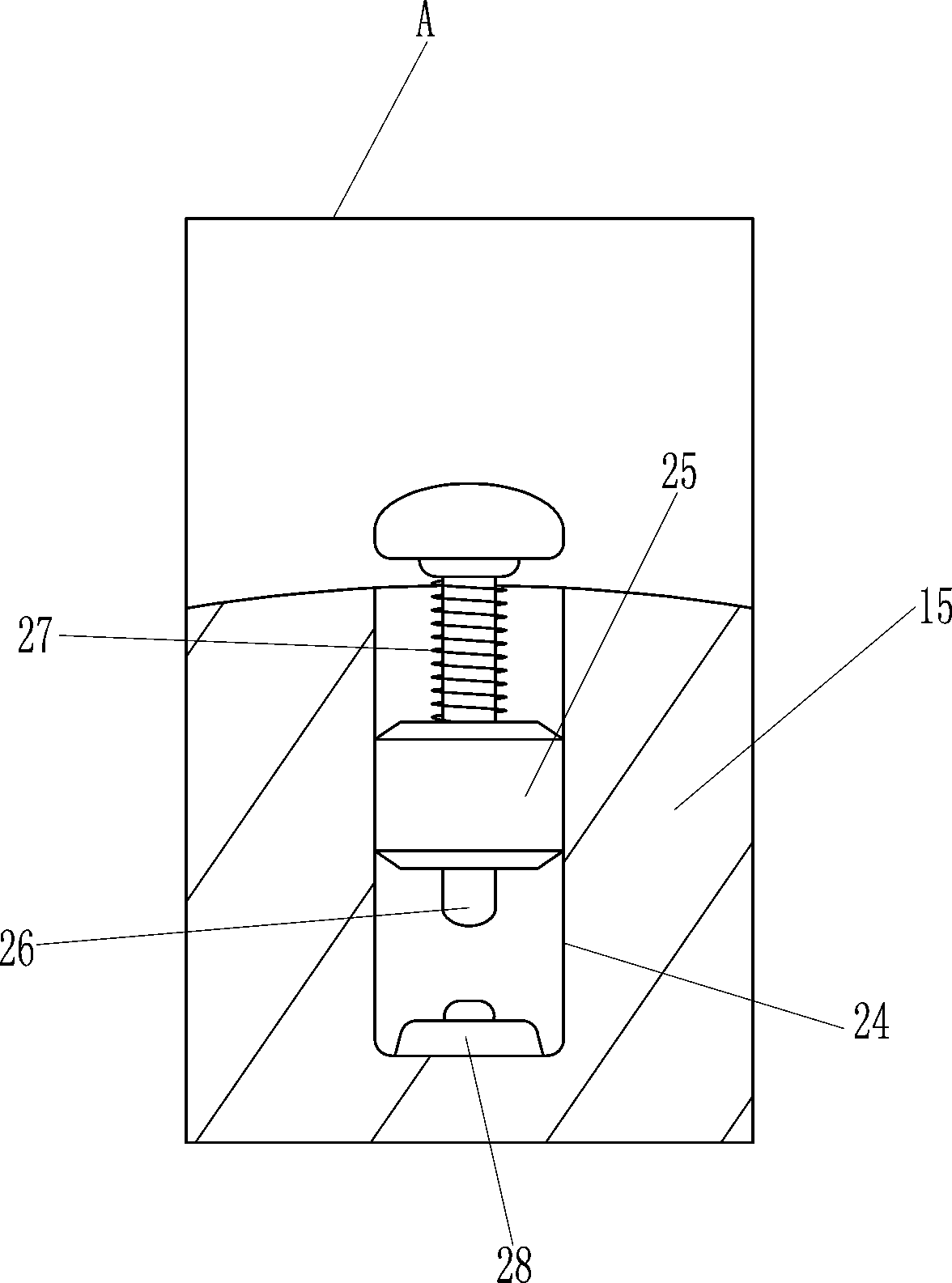
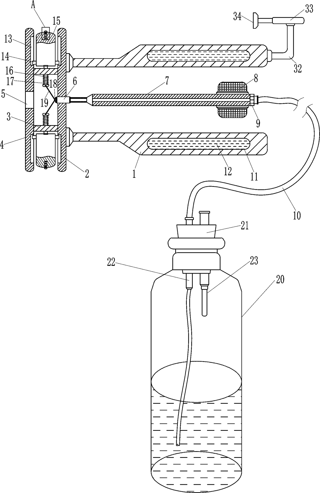
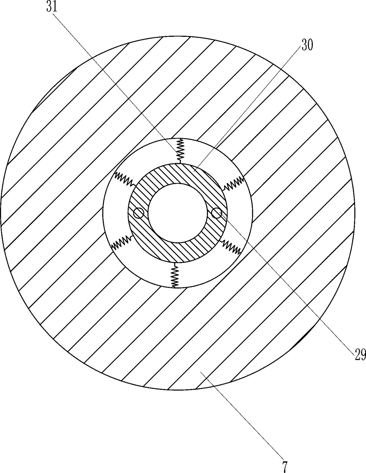
[0019] A kind of exhaust gas collection equipment for automobile troubleshooting, such as Figure 1-3 As shown, it includes a cross bar 1, a first connecting plate 2, a connecting rod 3, a second connecting plate 4, a first nut 6, a long hollow bolt 7, a handle 8, a second nut 9, a bolt hose 10, Heat-absorbing liquid 12, slide rail 13, slider 14, baffle plate 15, connecting rod 16, first compression spring 17, mounting block 18, rotating rod 19, exhaust gas treatment bottle 20, rubber plug 21, intake pipe 22 and exhaust Pipe 23, the first connecting plate 2 is connected to the left end of the horizontal bar 1 on the upper and lower sides, the upper and lower parts on the left side of the first connecting plate 2 are connected to the connecting rod 3, and the left end of the connecting rod 3 on the upper and lower sides is connected to the second connecting plate 4. There is a first opening 5 in the middle of the second connecting plate 4, a first nut 6 is embedded in the middl...

Embodiment 2

[0021] A kind of exhaust gas collection equipment for automobile troubleshooting, such as Figure 1-3As shown, it includes a cross bar 1, a first connecting plate 2, a connecting rod 3, a second connecting plate 4, a first nut 6, a long hollow bolt 7, a handle 8, a second nut 9, a bolt hose 10, Heat-absorbing liquid 12, slide rail 13, slider 14, baffle plate 15, connecting rod 16, first compression spring 17, mounting block 18, rotating rod 19, exhaust gas treatment bottle 20, rubber plug 21, intake pipe 22 and exhaust Pipe 23, the first connecting plate 2 is connected to the left end of the horizontal bar 1 on the upper and lower sides, the upper and lower parts on the left side of the first connecting plate 2 are connected to the connecting rod 3, and the left end of the connecting rod 3 on the upper and lower sides is connected to the second connecting plate 4. There is a first opening 5 in the middle of the second connecting plate 4, a first nut 6 is embedded in the middle...

Embodiment 3

[0024] A kind of exhaust gas collection equipment for automobile troubleshooting, such as Figure 1-3 As shown, it includes a cross bar 1, a first connecting plate 2, a connecting rod 3, a second connecting plate 4, a first nut 6, a long hollow bolt 7, a handle 8, a second nut 9, a bolt hose 10, Heat-absorbing liquid 12, slide rail 13, slider 14, baffle plate 15, connecting rod 16, first compression spring 17, mounting block 18, rotating rod 19, exhaust gas treatment bottle 20, rubber plug 21, intake pipe 22 and exhaust Pipe 23, the first connecting plate 2 is connected to the left end of the horizontal bar 1 on the upper and lower sides, the upper and lower parts on the left side of the first connecting plate 2 are connected to the connecting rod 3, and the left end of the connecting rod 3 on the upper and lower sides is connected to the second connecting plate 4. There is a first opening 5 in the middle of the second connecting plate 4, a first nut 6 is embedded in the middl...


PUM


Abstract

The invention relates to tail gas collecting equipment, in particular to tail gas collecting equipment for automotive fault overhauling. The tail gas collecting equipment which is used for automotivefault overhauling, convenient to operate and better in tail gas collecting effect is provided in order to solve the technical problems. According to the technical scheme, the tail gas collecting equipment for automotive fault overhauling comprises cross rods, a first connecting plate, connecting rods, a second connecting plate, a first nut and a long hollow bolt, wherein the first connecting plateis connected with the left ends of the cross rods at the upper part and the lower part; the connecting rods are connected with the upper part and the lower part of the left side of the first connecting plate; the second connecting plate is connected with the left ends of the connecting rods at the upper part and the lower part. A maintenance worker rotates a rotating handle to enable baffle plates at the upper part and the lower part to move to the outer side to be contacted with the top and the bottom of an automobile pipeline respectively, then parts on the left sides of the cross rods aremixed in the automobile pipeline, the automobile is started, maintenance work is performed, tail gas finally enters a waste gas treatment bottle through a first opening and is subjected to a reactionwith alkaline liquid, and the tail gas purification effect is realized.

Description

technical field [0001] The invention relates to an exhaust gas collection device, in particular to an exhaust gas collection device for automobile troubleshooting. Background technique [0002] With the development of the economy, the sales of automobiles in my country have continued to grow rapidly in recent years, and the number of automobiles has continued to rise, which not only leads to increasing oil consumption and excessive energy consumption, but also the exhaust gas emitted by automobiles has brought great harm to the environment. , the air is seriously polluted, which has a great impact on the human body. Therefore, the government calls for the control of vehicle exhaust emissions. The exhaust gas collection effect is not good, so many repair shops are not equipped with corresponding equipment. Contents of the invention [0003] In order to overcome the disadvantages of complex operation process and poor exhaust gas collection effect of traditional exhaust gas co...

Claims


Application Information

Patent Timeline
Patent Type & Authority Applications(China)
IPC IPC(8): B01D53/92B01D53/40B08B15/00B08B15/04G10K11/16
CPCB01D53/40B01D53/92B01D2258/01B08B15/00B08B15/04G10K11/16
Inventor 付兴旺
Owner 付安英
Why Eureka
Try Eureka