Image forming apparatus and image forming method capable of generating stable transfer electric field

a technology of image forming apparatus and electric field, which is applied in the direction of electrographic process apparatus, instruments, optics, etc., can solve the problems of reducing transfer efficiency, forming and affecting the quality of the image, so as to achieve the effect of reducing the transfer efficiency and reducing the formation of a faulty toner imag

Inactive Publication Date: 2009-05-14
RICOH KK
View PDF1 Cites 29 Cited by
  • Summary
  • Abstract
  • Description
  • Claims
  • Application Information

AI Technical Summary

Benefits of technology

[0012]This specification further describes below an image forming method according to an exemplary embodiment of the present invention. In one exemplary embodiment of the present invention, the image forming method includes carrying a toner image with an image carrier, applying a voltage to a transfer electric field generator with a voltage application member serving as a voltage applier and contacting the transfer electric field generator, and measuring a surface potential of the transfer electric field generator with a potential measurement device when a predetermined first time period elapses after the voltage application member applies the voltage to the transfer electric field generator. The image forming method further includes connecting a constant-voltage power source to at least one transfer member using a switch to change the voltage applier from the voltage application member to the at least one transfer member, applying a voltage to the transfer electric field generator with the at least one ...

Problems solved by technology

Accordingly, the transfer bias applied by the transfer member to the transfer electric field generator changes, resulting in decreased transfer efficiency and formation of a faulty toner image.
However, such measurements may not be precise due to changes in speed of an image forming operation and measurement error caused by movement of th...

Method used


Image

  • Image forming apparatus and image forming method capable of generating stable transfer electric field
  • Image forming apparatus and image forming method capable of generating stable transfer electric field
  • Image forming apparatus and image forming method capable of generating stable transfer electric field

Examples


Embodiment Construction

[0034]In describing exemplary embodiments illustrated in the drawings, specific terminology is employed for the sake of clarity. However, the disclosure of this specification is not intended to be limited to the specific terminology so selected and it is to be understood that each specific element includes all technical equivalents that operate in a similar manner.

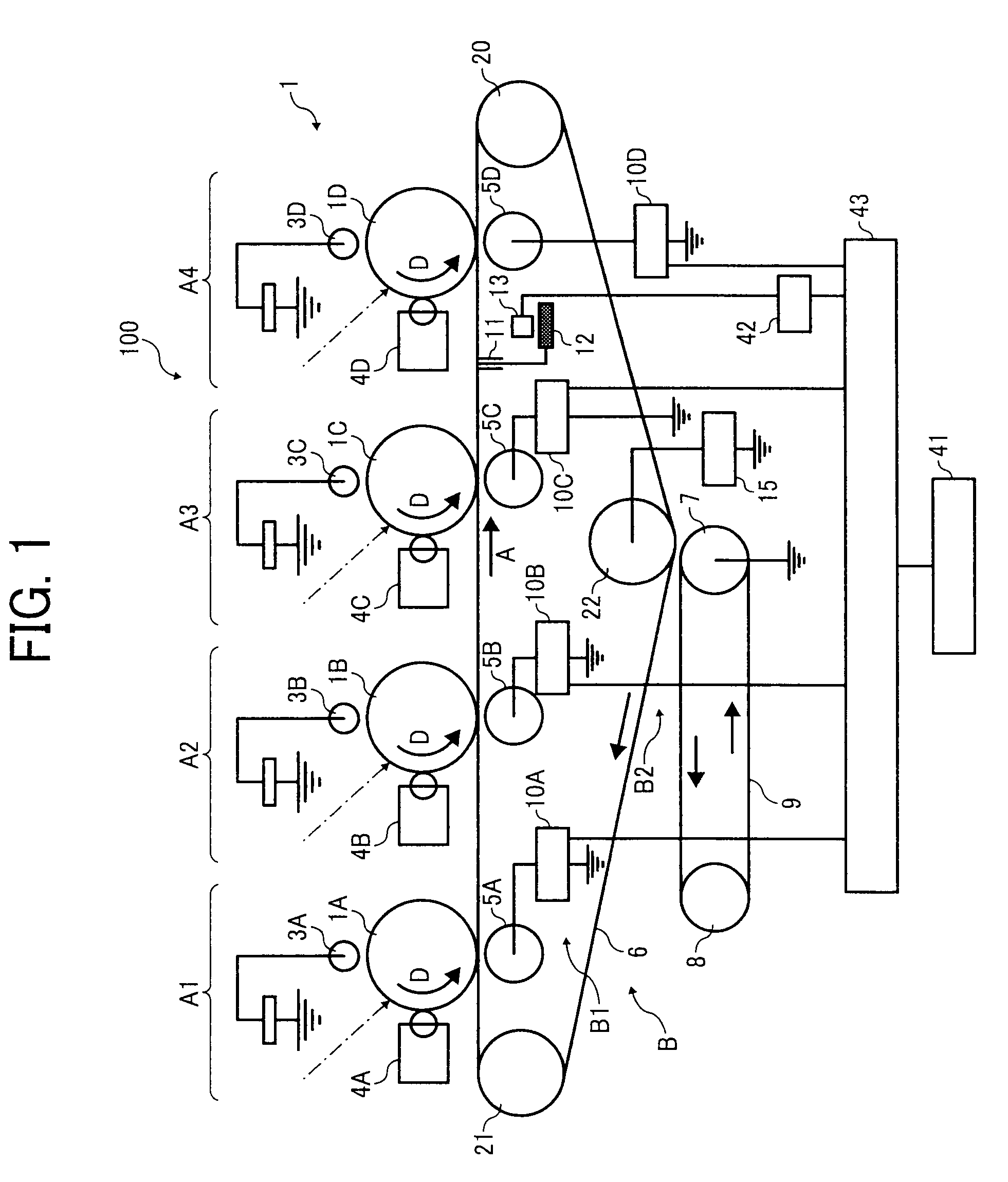
[0035]Referring now to the drawings, wherein like reference numerals designate identical or corresponding parts throughout the several views, in particular to FIG. 1, an image forming apparatus 100 according to an exemplary embodiment of the present invention is explained.

[0036]As illustrated in FIG. 1, the image forming apparatus 100 includes an image forming device 1, a timer 41, a recording member 42, and a controller 43. The image forming device 1 includes image forming units A1, A2, A3, and A4 and a transfer device B. The image forming units A1, A2, A3, and A4 include photoconductive drums 1A, 1B, 1C, and 1D, charging...


PUM


Abstract

An image forming apparatus includes an image carrier for carrying a toner image and a transfer device. In the transfer device, a voltage applier applies a predetermined voltage to a transfer electric field generator. A potential measurement device measures a surface potential of the transfer electric field generator when a predetermined time period elapses after the voltage applier applies the predetermined voltage to the transfer electric field generator. A controller determines a transfer bias to be applied by at least one transfer member to the transfer electric field generator based on the measured surface potential of the transfer electric field generator. The at least one transfer member applies the transfer bias to the transfer electric field generator to generate a transfer electric field. The toner image is transferred from the image carrier onto a toner image receiver by the transfer electric field generated by the transfer electric field generator.

Description

CROSS-REFERENCE TO RELATED APPLICATIONS[0001]The present application is based on and claims priority to Japanese Patent Application Nos. 2007-295110, filed on Nov. 14, 2007, and 2008-125090, filed on May 12, 2008 in the Japan Patent Office, the entire contents of each of which are hereby incorporated herein by reference.BACKGROUND OF THE INVENTION[0002]1. Field of the Invention[0003]Exemplary aspects of the present invention relate to an image forming apparatus and an image forming method, and more particularly, to an image forming apparatus and an image forming method using the image forming apparatus for controlling a voltage of an electric field to transfer a toner image.[0004]2. Description of the Related Art[0005]Related-art image forming apparatuses, such as copiers, facsimile machines, printers, or multifunction printers having at least one of copying, printing, scanning, and facsimile functions, typically form a color image on a recording medium (e.g., a transfer sheet) base...

Claims


Application Information

Patent Timeline
IPC IPC(8): G03G15/16G03G13/16
CPCG03G15/1675G03G2215/1614G03G2215/0129
Inventor AOKI, SHINJIIIMURA, HARUO
Owner RICOH KK
Why Eureka
Try Eureka