Fastener and fitting based sensing methods

a technology of fastener and fitting, applied in the direction of magnetic property measurement, material magnetic variables, instruments, etc., can solve the problems of lack of grip tolerance, preloading of fasteners, inconsistency in clamping, etc., and achieve the effect of enhancing the sensitivity of the response and enhancing the sensitivity of the test material condition

Active Publication Date: 2007-01-11
JENTEK SENSORS
View PDF53 Cites 23 Cited by
  • Summary
  • Abstract
  • Description
  • Claims
  • Application Information

AI Technical Summary

Benefits of technology

[0018] The fastener may further comprise an indicator layer that enhances sensitivity to the test material condition. Electrical connections to the conductor may be made through the head of the fastener. The fastener may comprise a channel to provide access to at least one conductor integrated into the fastener, and inserting a connector into the channel to contact a conductor. The channel may be in the form of a c

Problems solved by technology

When using these fasteners, problems include inconsistency in the clamp-up, preloading of the fasteners and lack-of-grip tolerance, as well as damage in the form of galling between the nut and bolt or damage at the load bearing surface.
These variations in fastener installation and damage eventually resulting from usage can lead to reduced aircraft life and substan

Method used


Image

  • Fastener and fitting based sensing methods
  • Fastener and fitting based sensing methods
  • Fastener and fitting based sensing methods

Examples


Embodiment Construction

[0037] A description of preferred embodiments of the invention follows.

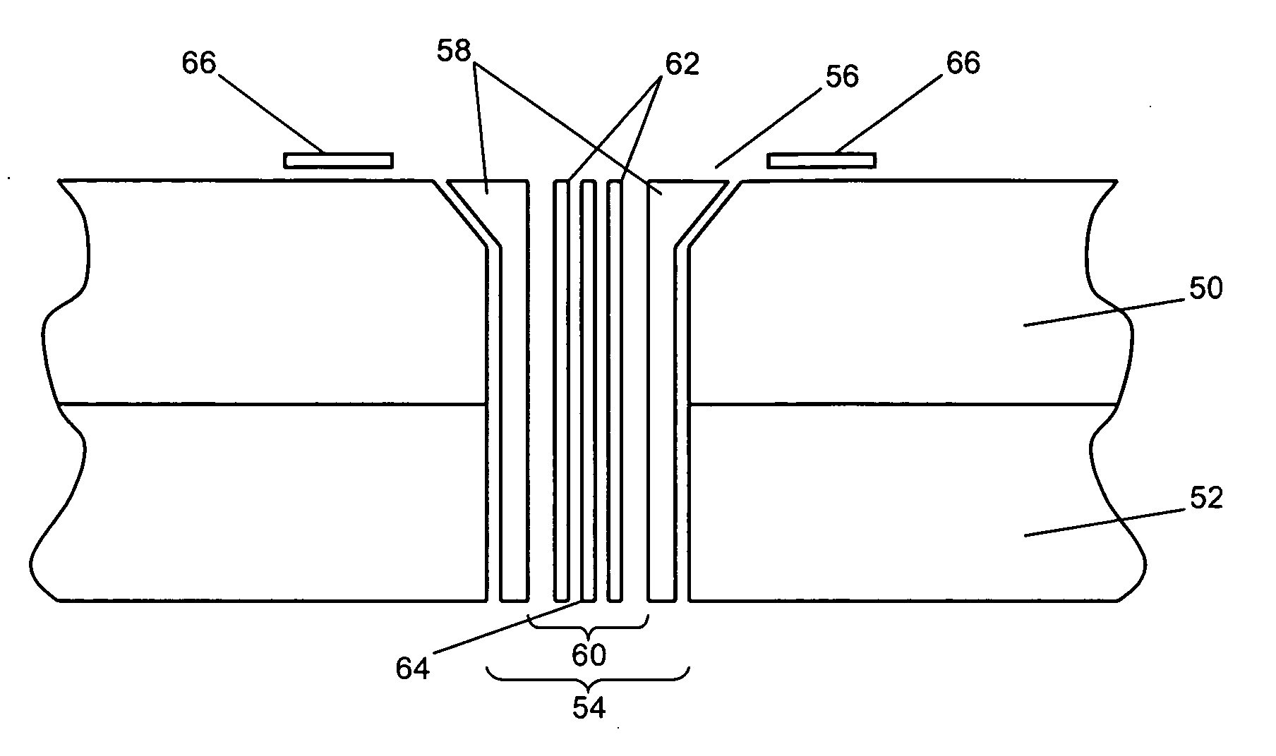
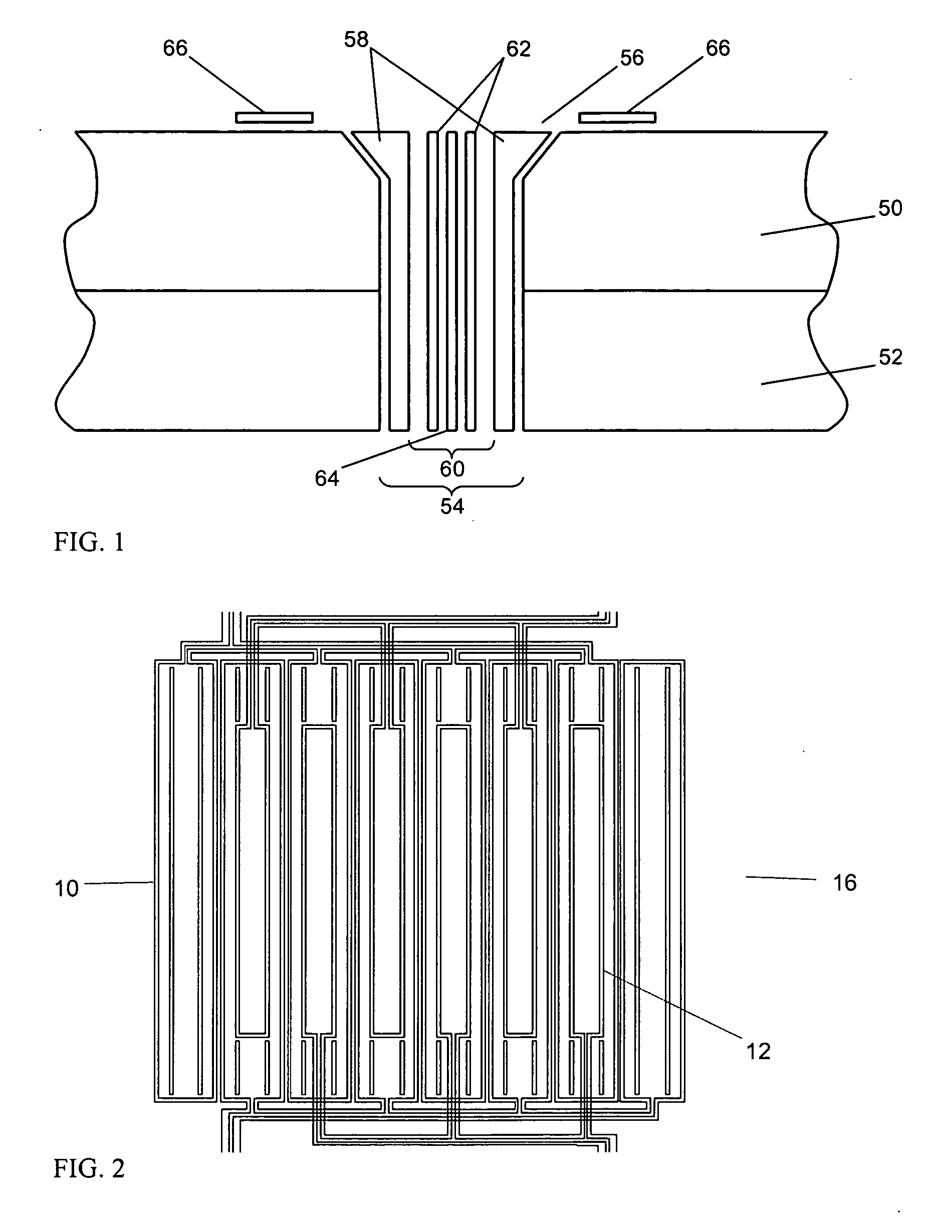
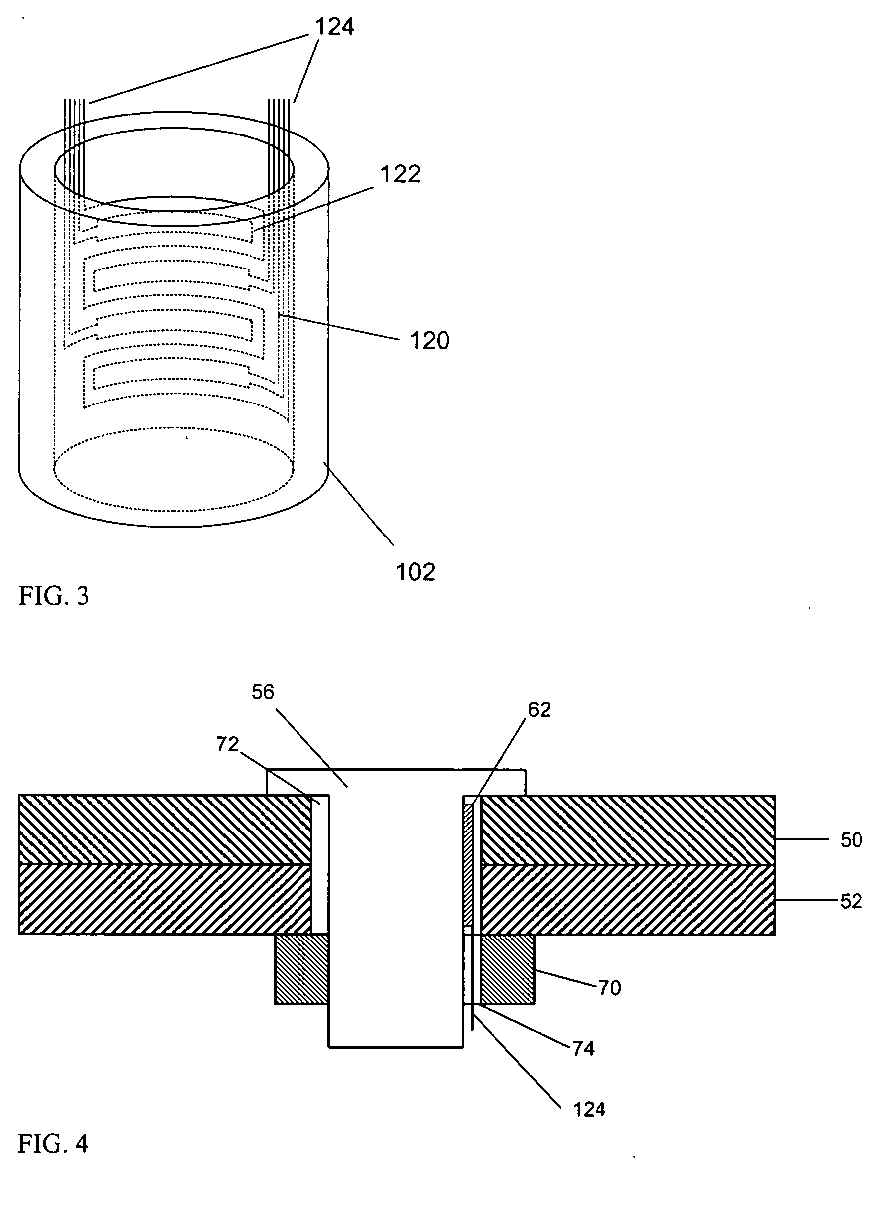
[0038] This invention addresses the need for enhanced monitoring of damage and usage states of materials, as well as material conditions resulting for example from processing during manufacture. This includes monitoring of damage, usage and material conditions during in-service use or processing, as well as scheduled or opportunistic inspection / sensing during down-time. Scheduled or opportunistic sensing might also be associated with specific naturally occurring states of the system or actuated states, such as temperature, load, or other measurable or controllable variables. The specific implementation addressed here is the use of sensors or sensor conductors embedded into fasteners, bushings, washers and fittings or other means and elements used for joining materials. Such joints tend to have two features: (1) load transfer or transfer of energy in some other form, such as thermal, and (2) enhanced access and m...


PUM


Abstract

Damage and usage conditions in the vicinity of fasteners in joined structures are nondestructively evaluated using the fasteners themselves. Sensors or sensor conductors are embedded in the fasteners or integrated within the fastener construct, either in the clearance gap between the fastener and the structure material or as an insert inside the shaft or pin of the fastener. The response of the material to an interrogating magnetic or electric field is then measured with drive and sense electrodes both incorporated into the fastener or with either drive or sense electrodes external to the fastener on the material surface. In another configuration, an electric current is applied to one or more fasteners and the electric potential is measured at locations typically between the driven electrodes applying the current. The potential is measured circumferentially around the fastener at locations on the material surface or across pairs of fasteners throughout or along the joint. The voltage or potential measurement electrodes may be collinear with the drive electrodes. State sensitive material layers can be added either to the fastener or the test material layers in order to enhance observability of the test material condition, such as the presence of a crack, mechanical stress, delamination, or disbond.

Description

RELATED APPLICATIONS [0001] This application claims the benefit of U.S. Provisional Application No. 60 / 693,347 filed on Jun. 22, 2005 and U.S. Provisional Application Ser. No. 60 / 696,625 filed on Jul. 5, 2005. The entire teachings of the above applications are incorporated herein by reference.BACKGROUND OF THE INVENTION [0002] The technical field of this invention is that of nondestructive materials characterization, particularly damage detection and monitoring using sensors. [0003] In some situations, such as on aircraft, the component material of interest has multiple layers and these layers are joined or clamped together by one or more fasteners. These fasteners can have a variety of geometries, but in many situations are threaded or press-fit into the holes in the material layers. When using these fasteners, problems include inconsistency in the clamp-up, preloading of the fasteners and lack-of-grip tolerance, as well as damage in the form of galling between the nut and bolt or ...

Claims


Application Information

Patent Timeline
IPC IPC(8): G01N27/82
CPCG01N27/82
Inventor GOLDFINE, NEIL J.GRUNDY, DAVID C.WASHABAUGH, ANDREW P.SHEIRETOV, YANKO K.SCHLICKER, DARRELL E.
Owner JENTEK SENSORS
Why Eureka
Try Eureka