Micromechanical potential sensor

a potential sensor and micro-mechanical technology, applied in the field of potential sensors, can solve the problems that the detection sensitivity cannot be made sufficiently high, and achieve the effects of improving the sensitivity, reducing the dimension, and increasing the area of the detection electrod

Inactive Publication Date: 2006-08-31
CANON KK
View PDF2 Cites 23 Cited by
  • Summary
  • Abstract
  • Description
  • Claims
  • Application Information

AI Technical Summary

Benefits of technology

[0016] According to the present invention, it is rendered possible to increase the area of the detection electrode, in comparison with that in the prior potential sensor utilizing the MEMS technology. It is therefore possible to improve the s

Problems solved by technology

However, in the MEMS potential sensor of the aforementioned structure, the detection sensitivity cannot be made sufficiently high beca

Method used


Image

  • Micromechanical potential sensor
  • Micromechanical potential sensor
  • Micromechanical potential sensor

Examples


example 1

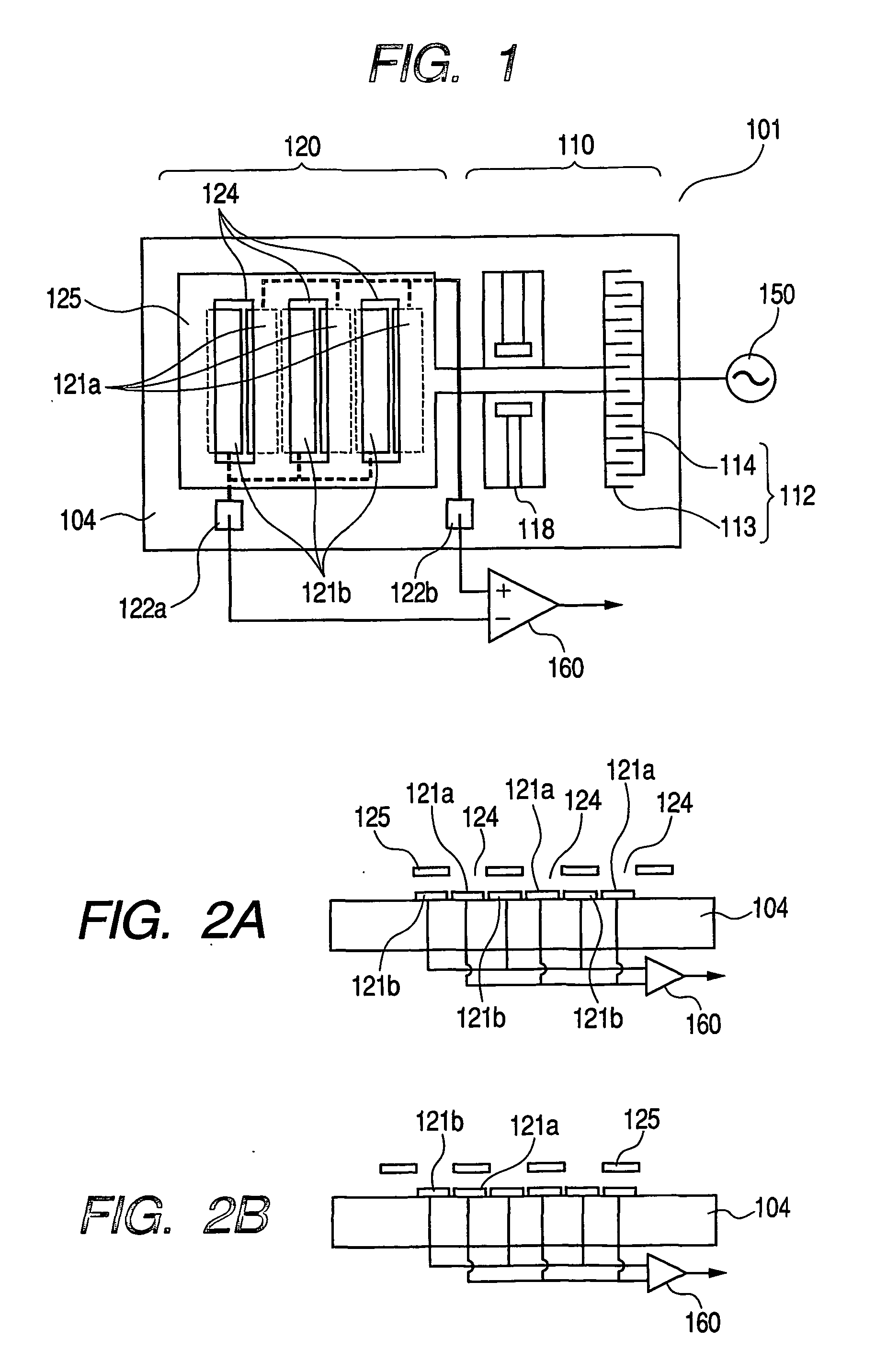
[0029]FIG. 1 is a plan view of a potential sensor of Example 1, and FIGS. 2A and 2B are cross-sectional views thereof. A potential sensor 101 is formed by a driver component 110 and a sensor component 120. These are formed by a MEMS technology on a substrate 104.

[0030] The driver component 110 is formed by a suspension 118 having a parallel hinge structure, and a comb-shaped electrostatic actuator 112. The comb-shaped electrostatic actuator 112 is a common mechanism for electrostatically driving a micro structure, and is composed of a movable electrode 113 supported by the suspension 118 and a fixed electrode 114 mounted on the substrate 104. The comb-shaped electrostatic actuator 112 is electrically connected to an electrostatic drive signal source 150. The movable electrode 113 is supported by the suspension 118 so as to be movable in a lateral direction in the drawing. The comb-shaped electrodes of the movable electrode 113 and those of the fixed electrode 114 are mutually meshi...

example 2

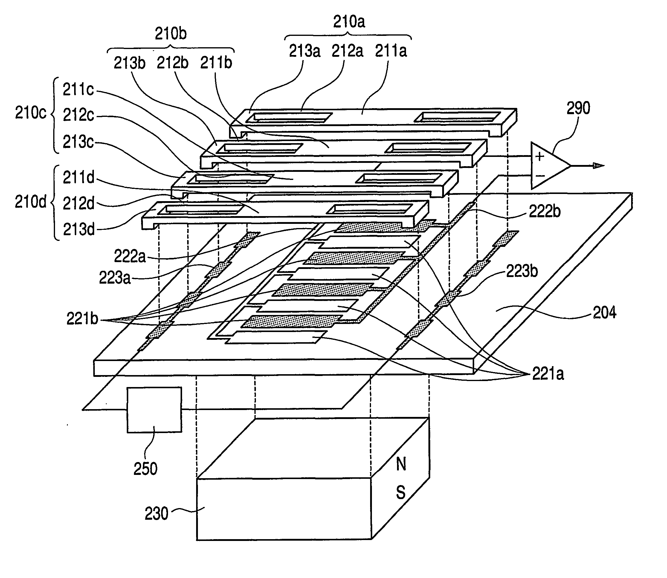
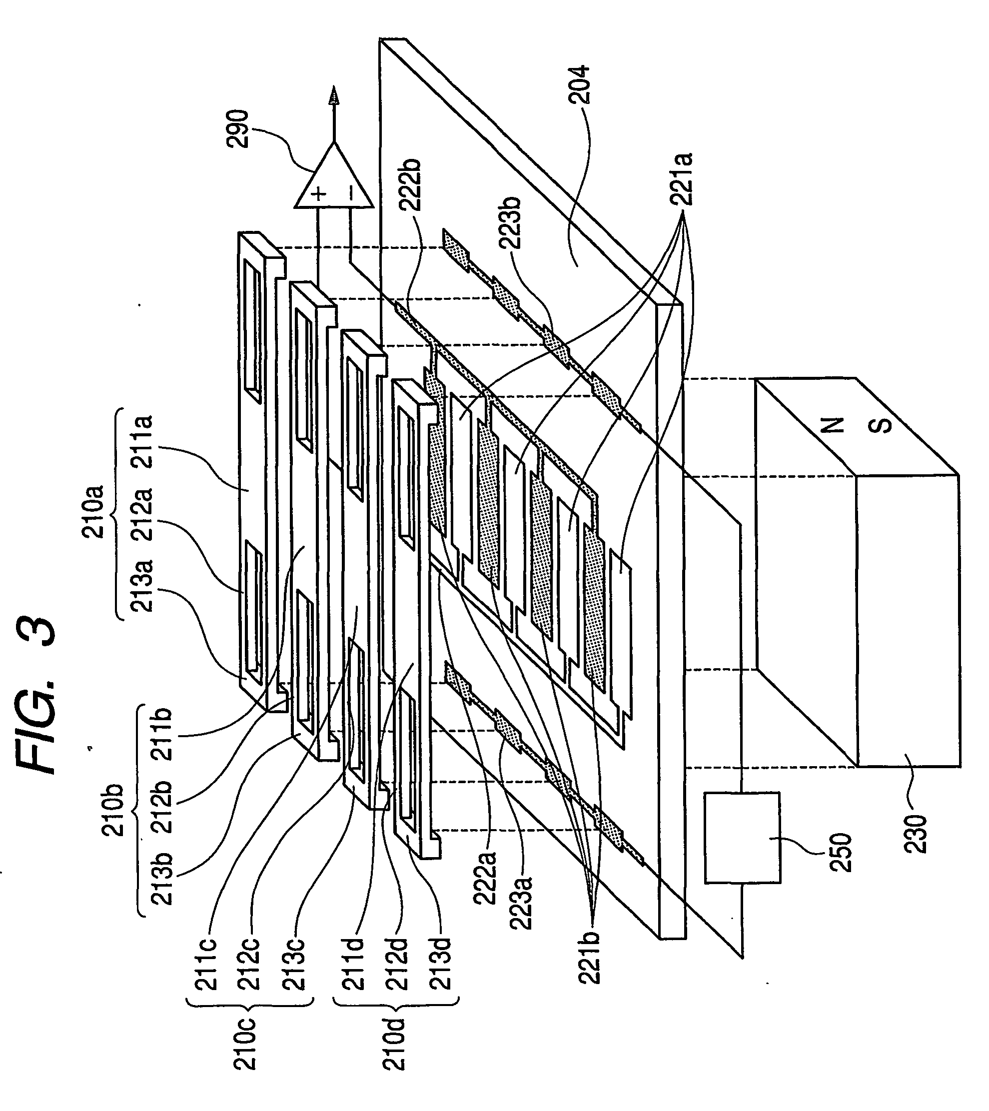
[0037]FIG. 3 is an exploded perspective view of a potential sensor of an example 2. On a substrate 204, detection electrode assemblies 221a, 221b, lead electrodes 222a, 222b for detection electrodes, and driving lead electrodes 233a, 233b are formed by patterning. The detection electrode assemblies 221a, 221b are comprised of sets of mutually distanced individual detection electrodes, and the detection electrodes of each set are electrically connected by the lead electrode 222a or 222b for the detection electrodes. Also the individual detection electrodes of the detection electrode assemblies 221a, 221b are arranged with such gaps as not to cause electrical shortcircuiting. Movable shutter units 210a to 210d are formed by mask members 211a to 211d, parallel hinge suspensions 212a to 212d and fixed members 213a to 213d, which are integrally formed with conductive materials. In the present example, the driving lead electrodes 223a, 223b are fixedly coupled with the fixed members 213a ...

example 3

[0045]FIG. 5 is an exploded perspective view of a potential sensor of an example 3. On a substrate 204, detection electrode assemblies 321a, 321b, lead electrodes 322a, 322b for detection electrodes, connecting electrodes 323a to 323c, and driving lead electrodes 324a, 324b are formed by patterning. The detection electrode assemblies 321a, 321b are comprised of sets of mutually distanced individual detection electrodes, and the detection electrodes of each set are electrically connected by the lead electrode 322a or 322b for the detection electrodes. Also the individual detection electrodes of the detection electrode assemblies 321a, 321b are arranged with such gaps as not to cause electrical shortcircuiting. Movable shutter units 310a to 310d are formed by mask members 311a to 311d, parallel hinge suspensions 312a to 312d and fixed members 313a to 313d, which are integrally formed with conductive materials. The connecting electrodes 323a to 323c and the driving lead electrodes 324a...


PUM


Abstract

A potential sensor (101) including first and second detection electrodes (121 a, b) opposed to an object of which a potential is to be measured, and a movable shutter (125) so positioned between the detection electrodes and the potential-measured object with gaps thereto; wherein the movable shutter can assume a first state and a second state, the first detection electrode is exposed to the potential-measured object wider when the movable shutter assumes the first state than when the movable shutter assumes the second state, and the second detection electrode is exposed to the potential-measured object narrower when the movable shutter assumes the first state than when the movable shutter assumes the second state.

Description

TECHNICAL FIELD [0001] The present invention relates to a potential sensor of non-contact type which can be easily prepared by a MEMS (micro electro mechanical systems) technology, and an image forming apparatus and a potential measuring method utilizing such potential sensor. BACKGROUND ART [0002] As a sensor for measuring a surface potential of a measured object, there is already known a variable capacitance potential sensor of mechanical type. FIG. 9 shows a principle of the variable capacitance potential sensor of mechanical type. A measured object 1099 has a potential V relative to a ground potential. A detection electrode 1021 is provided in an opposed relationship thereto, and a movable shutter 1025 is provided immediately above the detection electrode 1021. When the movable shutter 1025 moves, an electrostatic capacitance C between the measured object 1099 and the detection electrode 1025 shows a variation. In the detection electrode 1021, a charge Q is induced according to ...

Claims


Application Information

Patent Timeline
IPC IPC(8): G01R29/12
CPCG01R15/165G01R29/12G01R29/24
Inventor YASUDA, SUSUMUYAGI, TAKAYUKIUSHIJIMA, TAKASHIZAITSU, YOSHITAKAICHIMURA, YOSHIKATSU
Owner CANON KK
Why Eureka
Try Eureka