
Detection of Corrosion Defects in Buried Pipelines Using Vertically Measured Pipe-To-Soil Potential

a technology of corrosion defect and pipeline, applied in weather/light/corrosion resistance, instruments, material analysis, etc., can solve the problems of coating degradation and exfoliation, corrosion avoidance techniques of the day cannot prevent corrosion, and metal surface of pipeline exposed to soil

Active Publication Date: 2015-07-23
SOUTHWEST RES INST
View PDF14 Cites 21 Cited by
  • Summary
  • Abstract
  • Description
  • Claims
  • Application Information

AI Technical Summary

Benefits of technology

This patent is about a method for detecting corrosion on buried pipelines and other corrosion-sensitive structures. The method uses measurements of potential differences between the pipeline and the soil to estimate the rate of corrosion. This is important for managing the integrity of buried pipelines, as they are often inaccessible for corrosion detection. The method can be performed using special probes inserted into the soil above the pipeline, and the data collected from these measurements can be used to calculate the corrosion rate at specific locations on the pipeline. Overall, this method provides a non-destructive and effective way to detect and measure corrosion on buried pipelines.

Problems solved by technology

However, even the best of today's corrosion avoidance techniques do not prevent corrosion at some point.
In the pipeline industry, defects in the pipeline coating are known as “holidays”, and result in the metal surface of the pipeline being exposed to the soil.
Furthermore, coatings can degrade and exfoliate, creating areas where the coating material is present but partially or wholly disbonded from the pipe, limiting protection from corrosion.
However, buried pipelines are not easily accessible for corrosion detection.

Method used


Image

  • Detection of Corrosion Defects in Buried Pipelines Using Vertically Measured Pipe-To-Soil Potential
  • Detection of Corrosion Defects in Buried Pipelines Using Vertically Measured Pipe-To-Soil Potential
  • Detection of Corrosion Defects in Buried Pipelines Using Vertically Measured Pipe-To-Soil Potential

Examples


Embodiment Construction

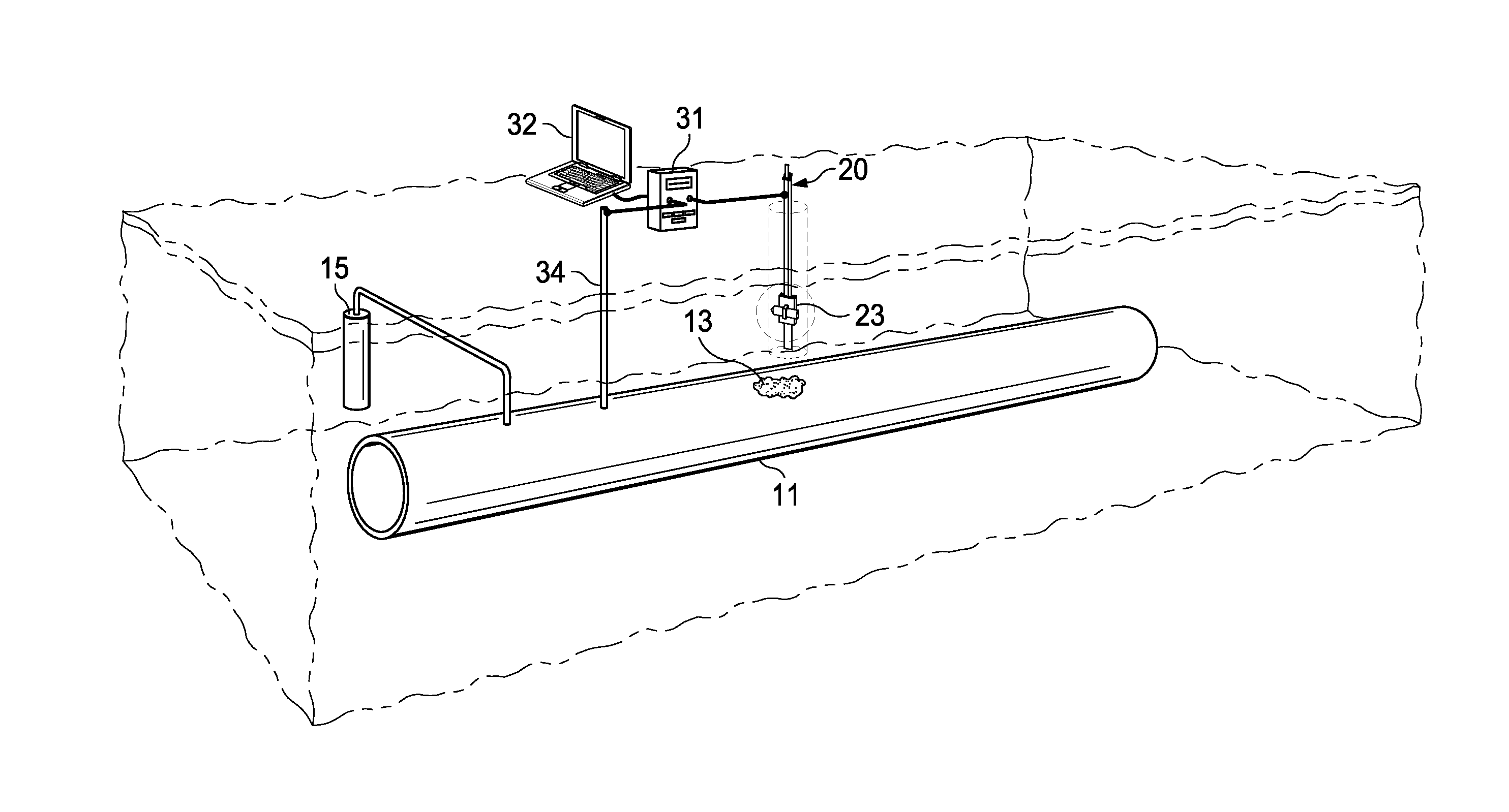
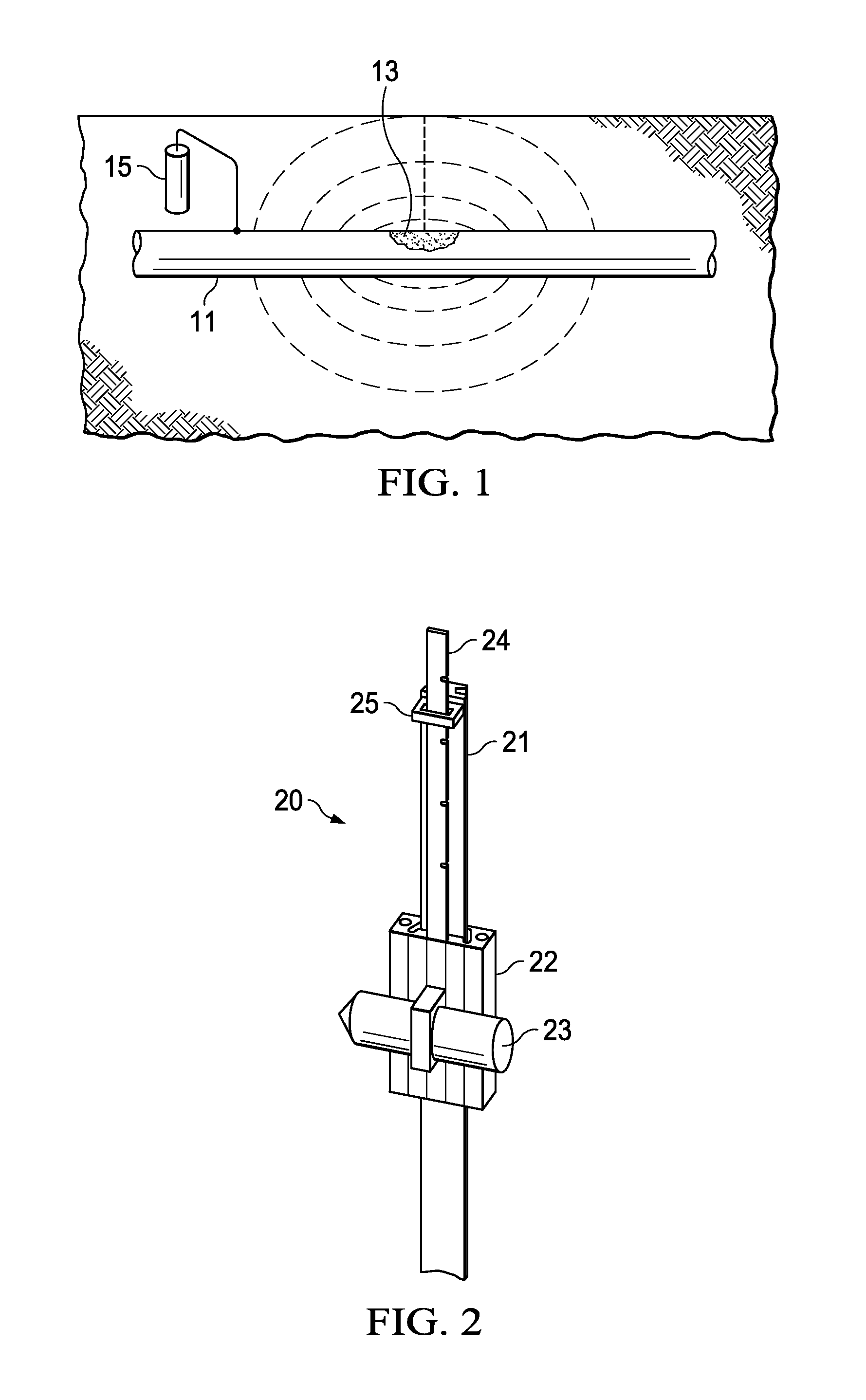
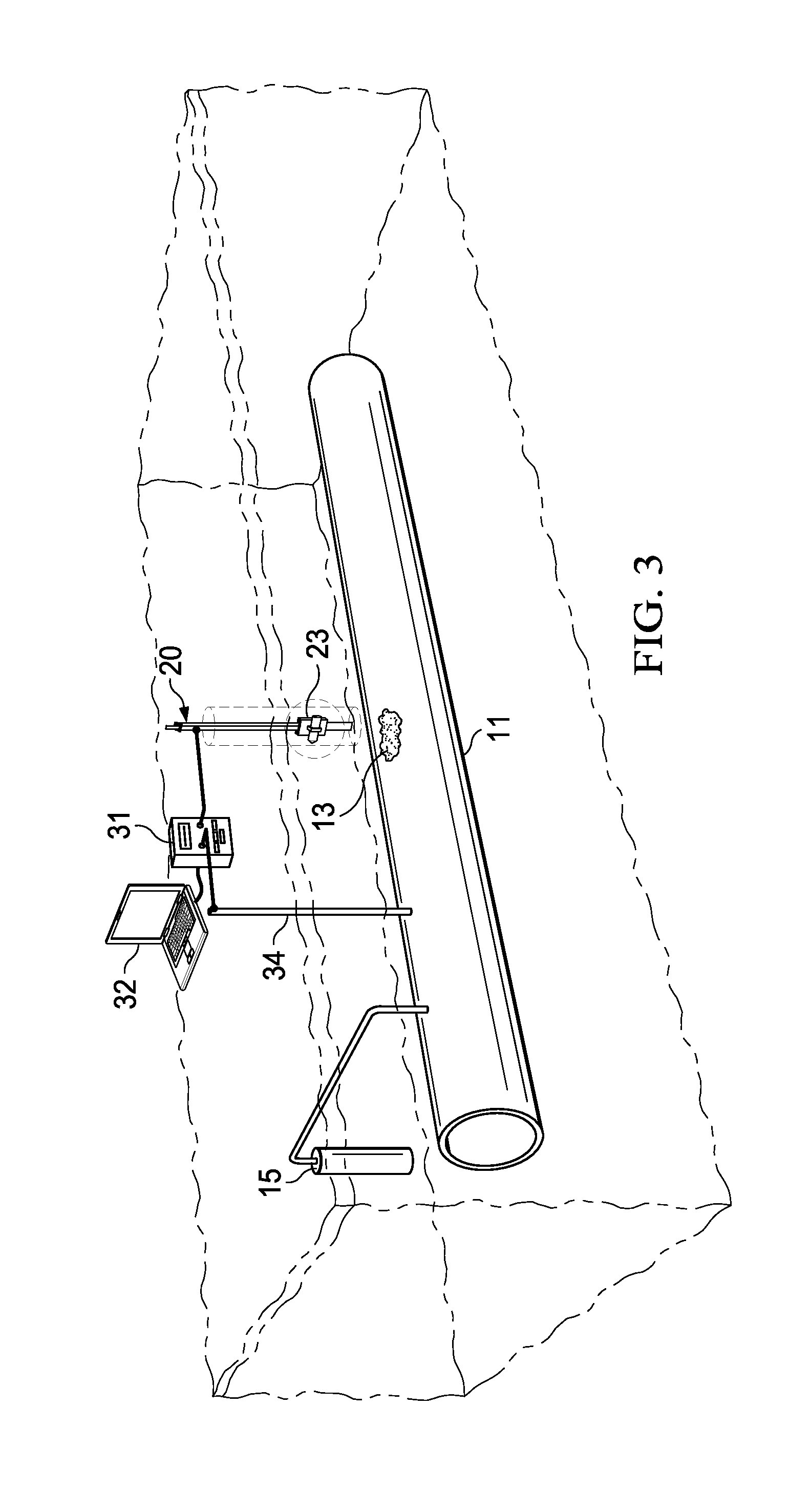
[0009]As stated in the Background, buried structures present particular problems for corrosion detection. Although the following description is in terms of detecting corrosion on a coated surface of a pipeline, the same concepts can be applied to detecting corrosion defects in any corrodible buried structure. The “corrodible” characteristic of the pipeline or buried structure means that at least a portion of its surface area is susceptible to metallic corrosion. The structure may be coated or uncoated, with “coated” referring to having paint or other covering material designed to protect the structure against corrosion.

[0010]The pipeline (or other structure) is assumed to be buried in soil. The term “soil” is used in a most general sense to mean any covering material, typically earth having some degree of moisture.

[0011]The following description is directed to in-situ corrosion rate estimation using vertically measured pipe-to-soil potentials over a buried pipeline under cathodic pr...


PUM

PropertyMeasurementUnit
diameteraaaaaaaaaa
corrosion rateaaaaaaaaaa
electric potentialaaaaaaaaaa

Abstract

A method for in-situ measuring the corrosion rate of a corroding site on an underground metal structure buried in soil, the structure being under cathodic protection. The structure-to-soil potential at varying depths above the pipeline is measured to a depth above, but not reaching the structure. These measurements are extrapolated to obtain data representing the structure-to-soil potential at the surface of the structure under the probe. The gradient of the electrical potential at this surface is used to calculate the corrosion rate of the defect. A special probe may be used to obtain the potential measurement data.

Description

TECHNICAL FIELD OF THE INVENTION[0001]This invention relates to detection and in-situ measurement of corrosion on buried pipelines (or other corrodible buried structures), and more particularly to using measurements of pipe-to-soil potential for such purposes.BACKGROUND OF THE INVENTION[0002]Buried pipelines are often coated and / or subjected to cathodic protection techniques in an effort to mitigate corrosion. Cathodic protection may be achieved by electrically connecting the pipeline to another more easily corroded metal to act as the anode of a simulated electrochemical cell. Another type of cathodic protection technique uses impressed currents; a current is applied to the pipeline to force the pipeline surface to act as a cathode.[0003]However, even the best of today's corrosion avoidance techniques do not prevent corrosion at some point. In the pipeline industry, defects in the pipeline coating are known as “holidays”, and result in the metal surface of the pipeline being expose...

Claims


Application Information

Patent Timeline
Patent Type & Authority Applications(United States)
IPC IPC(8): G01N17/00G01N17/04
CPCG01N17/04G01N17/006
Inventor SHUKLA, PAVAN K.DASGUPTA, BISWAJIT
Owner SOUTHWEST RES INST
Learn More