Hybrid bone fixation element and methods of using the same

a technology of bone fixation element and hybrid bone, which is applied in the field of hybrid bone fixation element, can solve the problems of little, if any, purchase, between the threads and the cancellous inner portion of the human bone, and achieve the effect of reducing the amount of purchas

Active Publication Date: 2009-05-14
DEPUY SYNTHES PROD INC
View PDF52 Cites 116 Cited by
  • Summary
  • Abstract
  • Description
  • Claims
  • Application Information

AI Technical Summary

Problems solved by technology

That is, the interaction between the threads and the cancellous inner portion of the human bone add little, if any, purchase as the cancellous inner portion is too soft for threadably engaging the threads of the bone screw.

Method used


Image

  • Hybrid bone fixation element and methods of using the same
  • Hybrid bone fixation element and methods of using the same
  • Hybrid bone fixation element and methods of using the same

Examples


Embodiment Construction

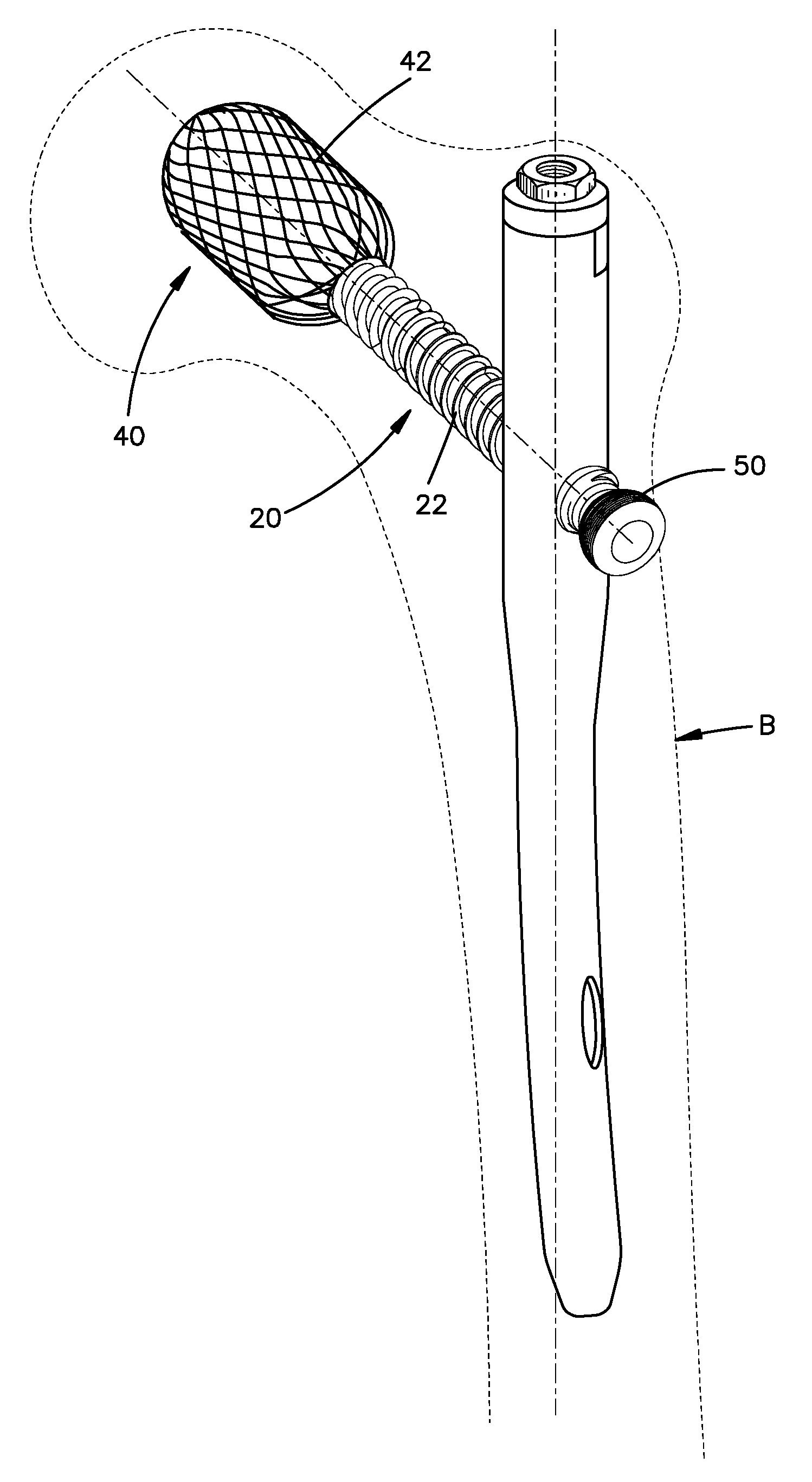
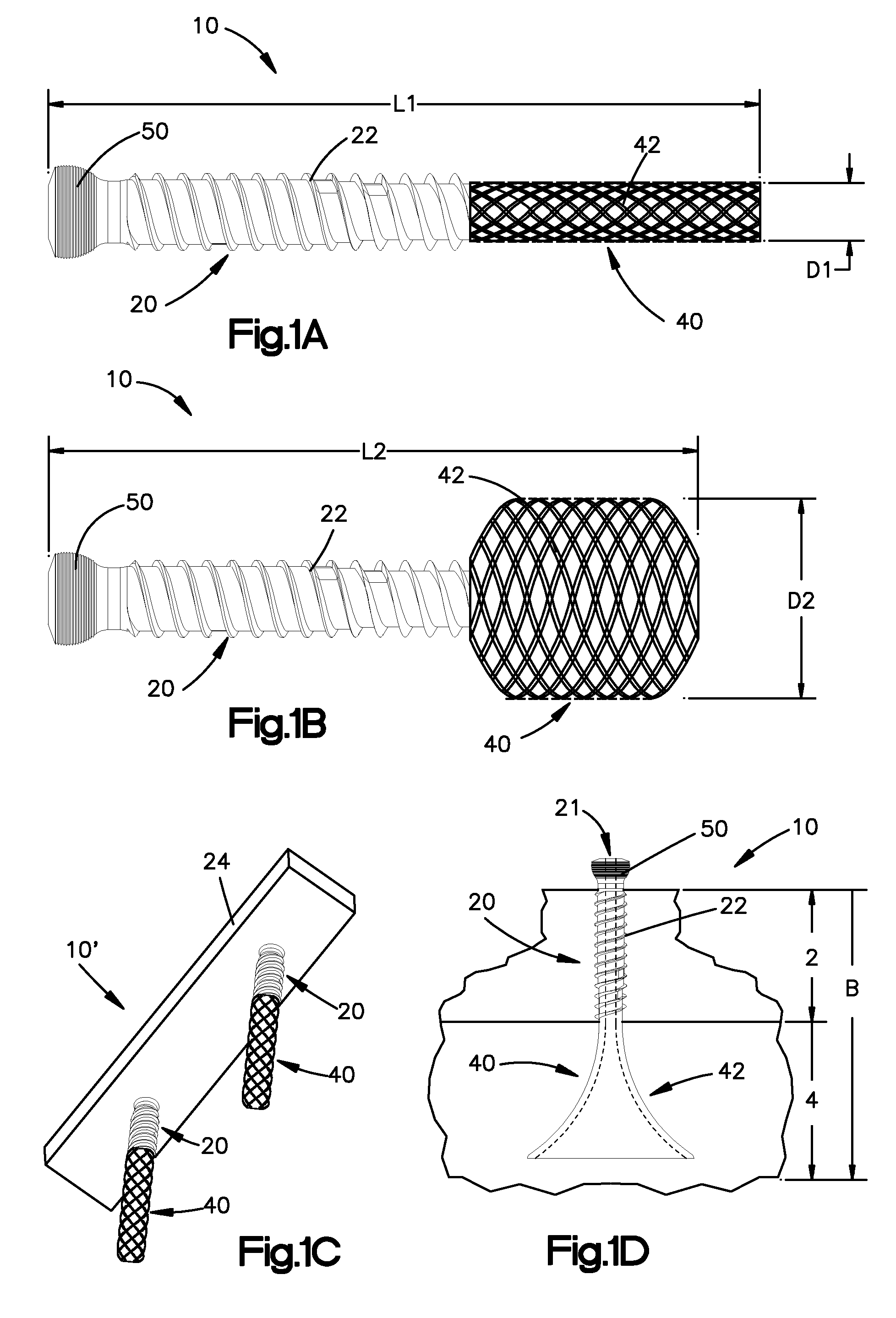
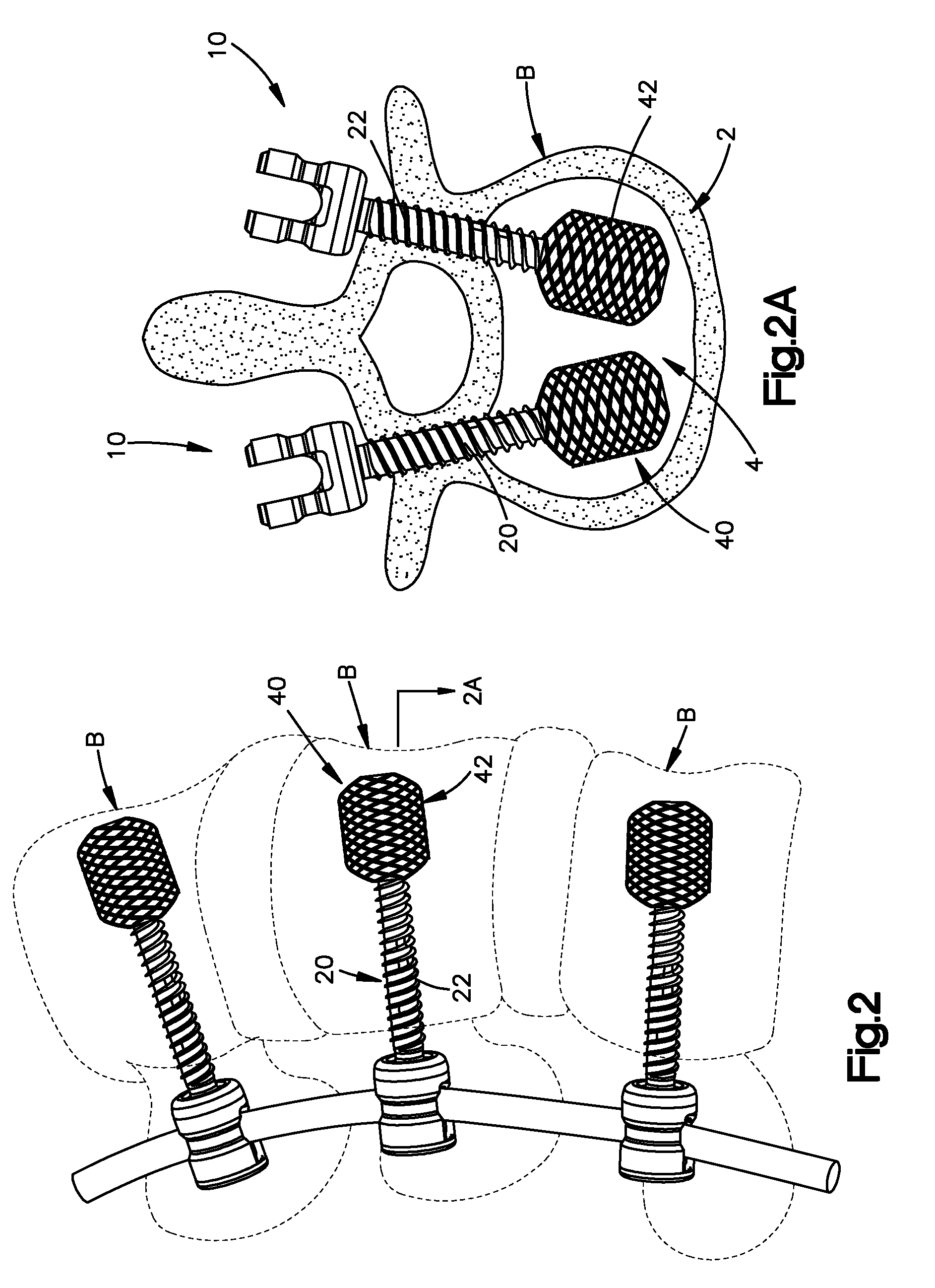
[0021]Certain terminology is used in the following description for convenience only and is not limiting. The words “right”, “left”, “lower” and “upper” designate directions in the drawings to which reference is made. The words “inwardly” and “outwardly” refer to directions toward and away from, respectively, the geometric center of the device and designated parts thereof. The words, “anterior”, “posterior”, “superior”, “inferior” and related words and / or phrases designate preferred positions and orientations in the human body to which reference is made and are not meant to be limiting. The terminology includes the above-listed words, derivatives thereof and words of similar import.

[0022]Certain exemplary embodiments of the invention will now be described with reference to the drawings. In general, such embodiments relate to a hybrid bone fixation element 10 for engaging a human bone B. The hybrid bone fixation element 10 preferably includes a first cortical bone contacting portion 2...


PUM


Abstract

The present invention is directed to a hybrid bone fixation element including a threaded proximal cortical bone contacting portion for threadably engaging the cortical portion of a human bone and a non-threaded expandable distal cancellous portion for engaging the cancellous portion of the human bone. The hybrid bone fixation element can be used, for example, as a pedicle screw, a bone screw or in any other type of bone fixation application.

Description

CROSS-REFERENCE TO RELATED APPLICATIONS[0001]This application claims the benefit of U.S. Provisional Application No. 60 / 987,973, filed on Nov. 14, 2007, titled “Hybrid Bone Screw,” the contents of which is hereby incorporated by reference in its entirety.BACKGROUND OF THE INVENTION[0002]Generally speaking, the human bone is formed by a hard, thinner cortical outer portion surrounding a softer cancellous inner portion. Convention bone screws include a threaded shaft for engaging and obtaining purchase in the bone. The bone screw may be manually inserted into the bone by, for example, a screw driver. In use, torque is applied to the bone screw to drive or rotate the screw so that it is inserted into the cortical and cancellous portions of the bone. However, generally speaking, substantially all, if not all, of the bone screw's purchase is achieved via the engagement of the threads with the cortical outer portion. That is, the interaction between the threads and the cancellous inner po...

Claims


Application Information

Patent Timeline
Patent Type & Authority Applications(United States)
IPC IPC(8): A61B17/56
CPCA61B17/68A61B17/7032A61B17/744A61B17/80A61B17/86A61F2/442A61B17/863A61B2017/8655A61F2/4455A61F2002/30579A61B17/7283A61B17/8625
Inventor TEISEN, JACQUESSTUCKI, SIMON
Owner DEPUY SYNTHES PROD INC
Why Eureka
Try Eureka