Heat exchanger with manifold strengthening protrusion

a technology of manifold and heat exchanger, which is applied in the direction of reinforcing means, stationary conduit assemblies, lighting and heating apparatus, etc., can solve the problems of increasing the overall manufacturing cost of a particular heat exchanger, premature failure or cracking etc., to improve the overall efficiency of the heat exchanger, improve the overall ability of the manifold, and high fluid pressure

Active Publication Date: 2009-05-21
DANA CANADA CORP
View PDF17 Cites 44 Cited by
  • Summary
  • Abstract
  • Description
  • Claims
  • Application Information

AI Technical Summary

Benefits of technology

[0005]In the present invention, a protrusion member is formed in the peripheral region of the plates of a stacked-plate heat exchanger in proximity to the manifold region to improve the overall ability of the manifold to withstand the high fluid pressures that are frequently encountered in these types of heat exchanger systems as well as to improve the overall efficiency of the heat exchanger by preventing undesirable bypass flow.

Problems solved by technology

However, as the plate pairs tend to be unsupported in the area of the manifolds, the heat exchanger in the area of the inlet and outlet openings tends to distort under the pressure of the fluid flowing therethrough and will often expand like an accordion or “bellows” in the manifold region.
The distortion that occurs in the manifold regions of the heat exchanger tends to lead to premature failure or cracking and leaking in the heat exchanger.
The additional surface area provided by the large area washer or reinforcing plate provides additional support to the typically unsupported area between plate pairs; however, these types of washers can be costly and therefore increase overall manufacturing costs associated with the particular heat exchanger.

Method used


Image

  • Heat exchanger with manifold strengthening protrusion
  • Heat exchanger with manifold strengthening protrusion
  • Heat exchanger with manifold strengthening protrusion

Examples


Embodiment Construction

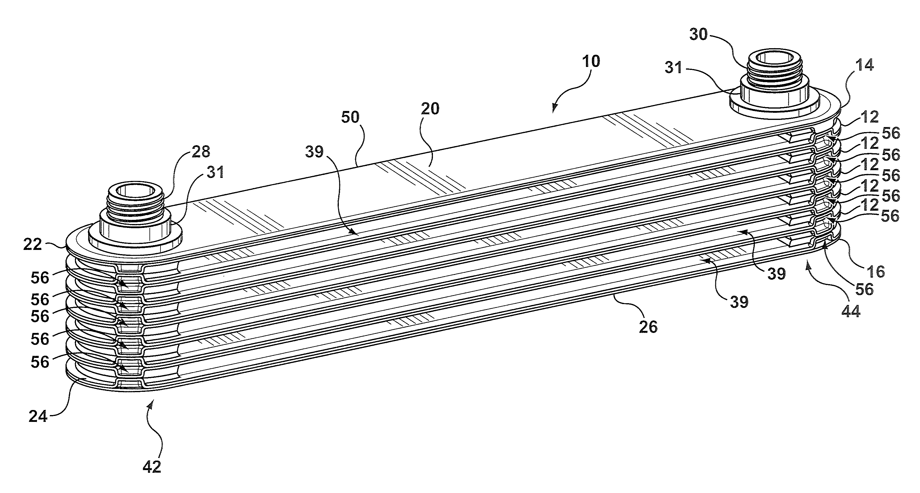
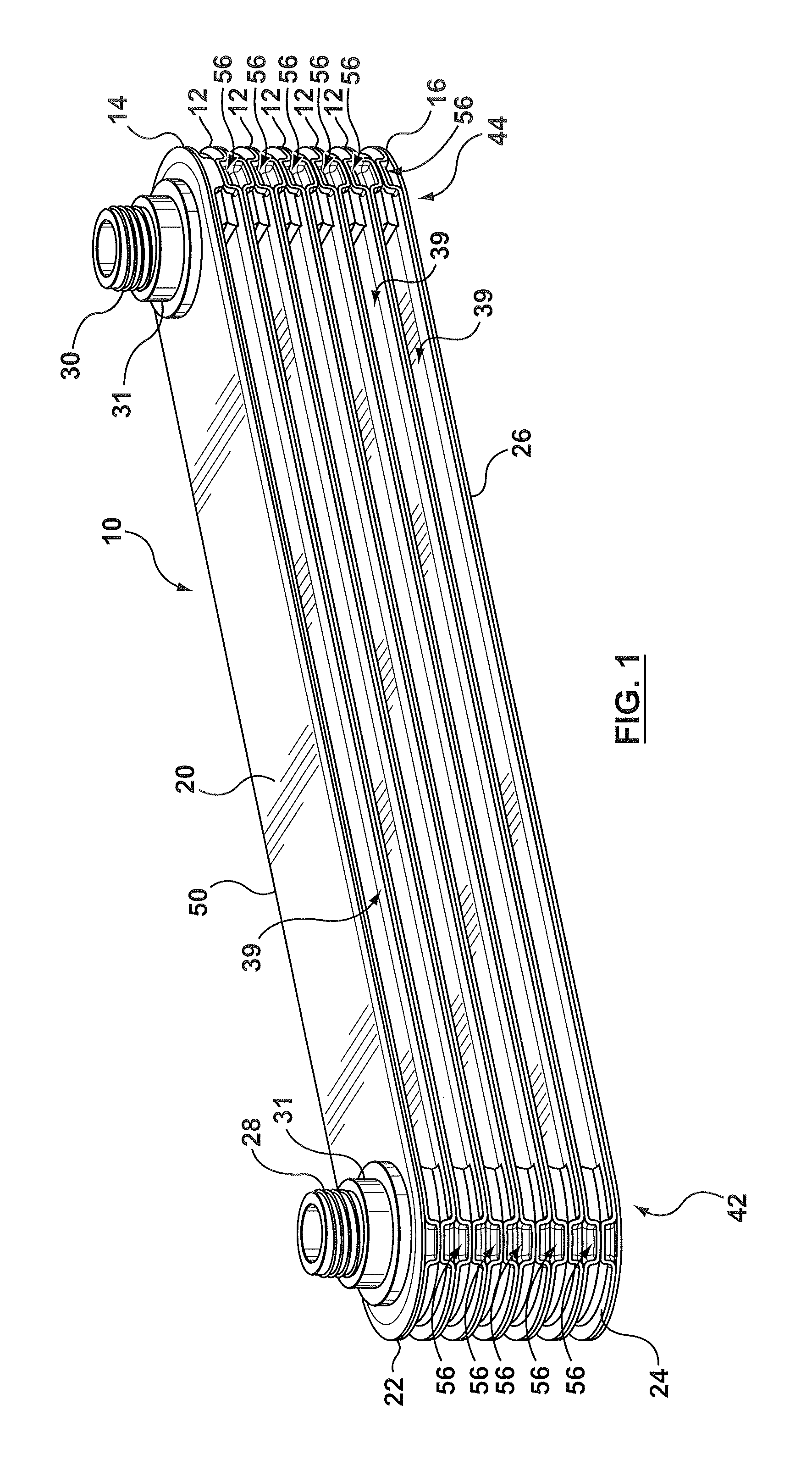
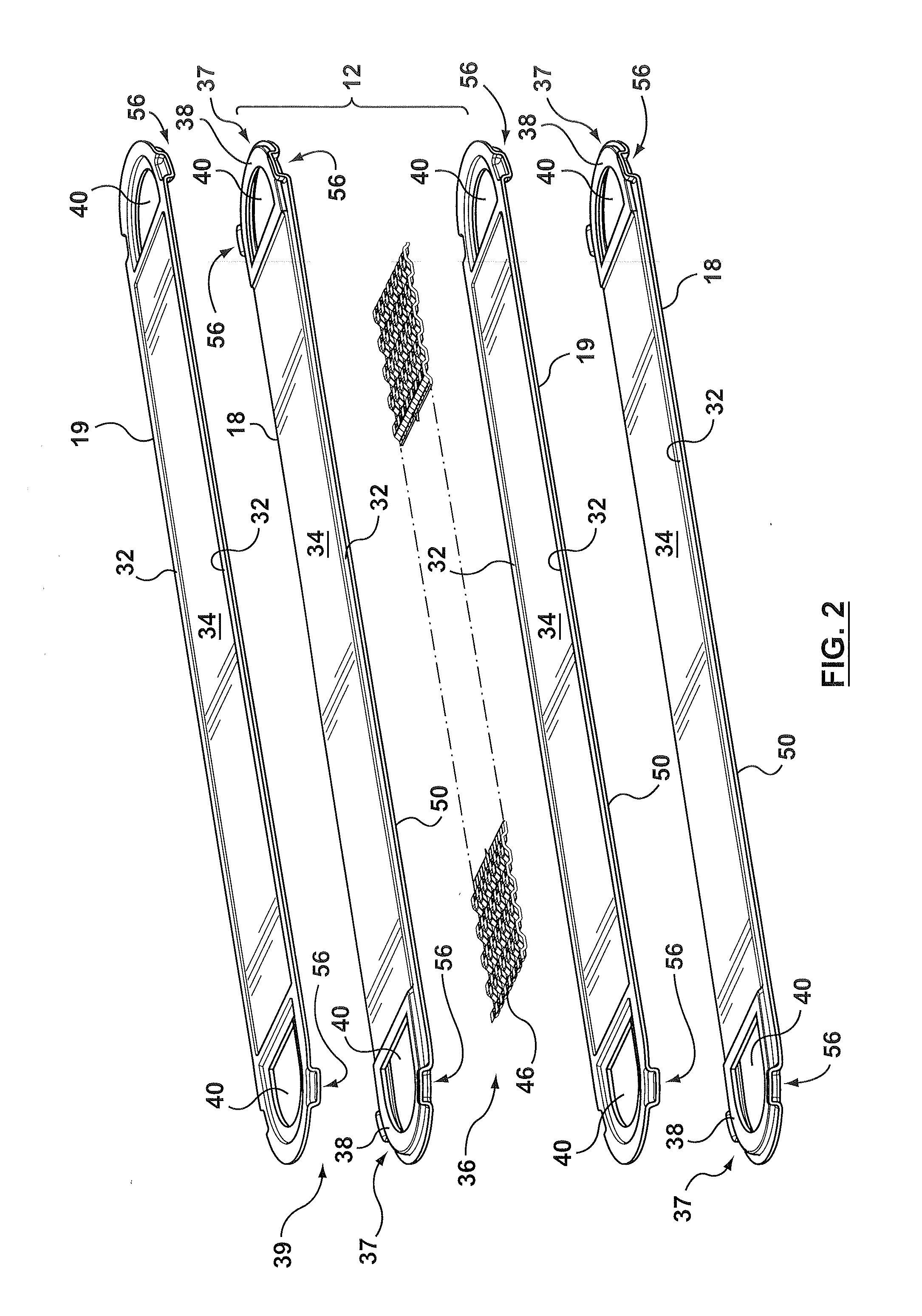
[0029]Referring to the drawings, there is shown in FIG. 1 a heat exchanger 10 according to one embodiment of the present invention. Heat exchanger 10 is formed of a plurality of stacked plate pairs 12, a top plate pair 14 and a bottom plate pair 16. Each plate pair 12 is identical and is comprised of first and second plates 18, 19. First and second plates 18, 19 are identical to each other and are arranged in a face-to-face relationship so that the second plate 19 is upside down with respect to the first plate 18. Top plate pair 14 is comprised of a first top plate 20 and a second plate 22 which is the same as one of the second plates 19 that form part of plate pairs 12. Bottom plate pair 16 has a first plate 24 which is the same as the first plate 18 that forms part of the plate pairs 12 and a bottom plate 26. Top plate 20 of the top plate pair 14 is generally a plain, flat plate having opposed openings or ports 31 formed therein for receiving inlet and outlet fittings or nipples 2...


PUM


Abstract

A plate type heat exchanger is disclosed having a plurality of stacked plate pairs made up of first and second plates. Each plate pair has opposed manifold members with respective inlet and outlet openings that are in registration to form respective inlet and outlet manifolds for the flow of a first fluid through a first set of fluid channels formed by the plate pairs, the manifold members spacing the plate pairs apart to form a second set of transverse flow channels for the flow of a second fluid. Each plate has a peripheral edge portion which seals the plates together to form the first set of fluid channels therebetween. A protrusion member is formed proximal to each of the manifold members, each protrusion member having a mating surface such that the protrusion members on the second plate of one plate pair align and abut with the protrusion members on the first plate of an adjacent plate pair thereby reinforcing and strengthening the manifold region of the heat exchanger to prevent the deformation or accordion of the manifold under pressure.

Description

FIELD OF THE INVENTION[0001]This invention relates to heat exchangers, and in particular to stacked plate heat exchangers as used particularly in the automotive industry.BACKGROUND OF THE INVENTION[0002]Stacked plate heat exchangers typically comprise a plurality of plate pairs stacked one on top of the other with each plate pair having opposed inlet and outlet openings such that when the plate pairs are stacked together, the inlet and outlet openings align to form inlet and outlet manifolds and thereby establish communication between fluid channels formed inside each plate pair. The plate pairs are usually joined together by brazing. However, as the plate pairs tend to be unsupported in the area of the manifolds, the heat exchanger in the area of the inlet and outlet openings tends to distort under the pressure of the fluid flowing therethrough and will often expand like an accordion or “bellows” in the manifold region. The distortion that occurs in the manifold regions of the heat...

Claims


Application Information

Patent Timeline
Patent Type & Authority Applications(United States)
IPC IPC(8): F28F13/12F28F3/00F28F3/02
CPCF28D1/0325F28F2225/08F28D1/0333F28F3/08F28F9/007
Inventor SHORE, CHRISTOPHER R.STORR, CINDY W.IZARD, JOHN W.KOZDRAS, MARK S.
Owner DANA CANADA CORP
Why Eureka
Try Eureka