Switch apparatus

a technology of switch and diaphragm, which is applied in the direction of electrical switches, contact mechanisms, electrical apparatus, etc., can solve the problems of short time-consuming and laborious, and the durability of the diaphragm is lost, so as to prevent the wear and tear of the diaphragm

Active Publication Date: 2009-05-21
NILES PARTS CO LTD
View PDF5 Cites 13 Cited by
  • Summary
  • Abstract
  • Description
  • Claims
  • Application Information

AI Technical Summary

Benefits of technology

[0023]In order to achieve the object that a contact housing portion should be kept liquid tight sealed and should have improved durability, a switch apparatus according to the present invention is mainly characterized by including: a switch case including a contact housing portion therein and a shaft hole opened to outside at one end thereof; a rod which is axially movable along the shaft hole and rotatably supported and whose outer distal end can abut on and engage with in the axial direction; an elastic member interposed between the switch case and the rod and biasing the rod in the extending and shrinking direction with respect to shaft hole; a fixed contact housed in the contact housing portion and fixed to the switch case, a movable contact which can reciprocally move between a position touching the fixed contact and a non-touching position; a diaphragm separating the shaft hole from the contact housing portion and being formed of a non-conducting material; a movable base supporting the movable contact and abutting on the diaphragm;
[0026]For this reason, the liquid tight state of the contact housing portion can be maintained by the diaphragm and the durability of the diaphragm can be prevented from wearing.

Problems solved by technology

However, in the switch apparatus 115 for detecting a differential lock state as described above, since the flange 119 of the rod 117 abuts on and engages with the rotating detecting plate 121 in the axial direction, the rod 117 rotates in an interlocking manner with the detecting plate 121 generates a sliding contact between the rod 117 and the diaphragm, which may produce a problem in that the diaphragm loses its durability in a short period of time.
The problem to be solved is that the contact housing portion being made liquid tight loses its durability.

Method used


Image

  • Switch apparatus
  • Switch apparatus
  • Switch apparatus

Examples


embodiment 1

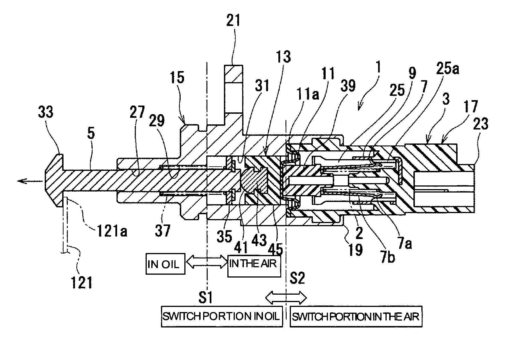
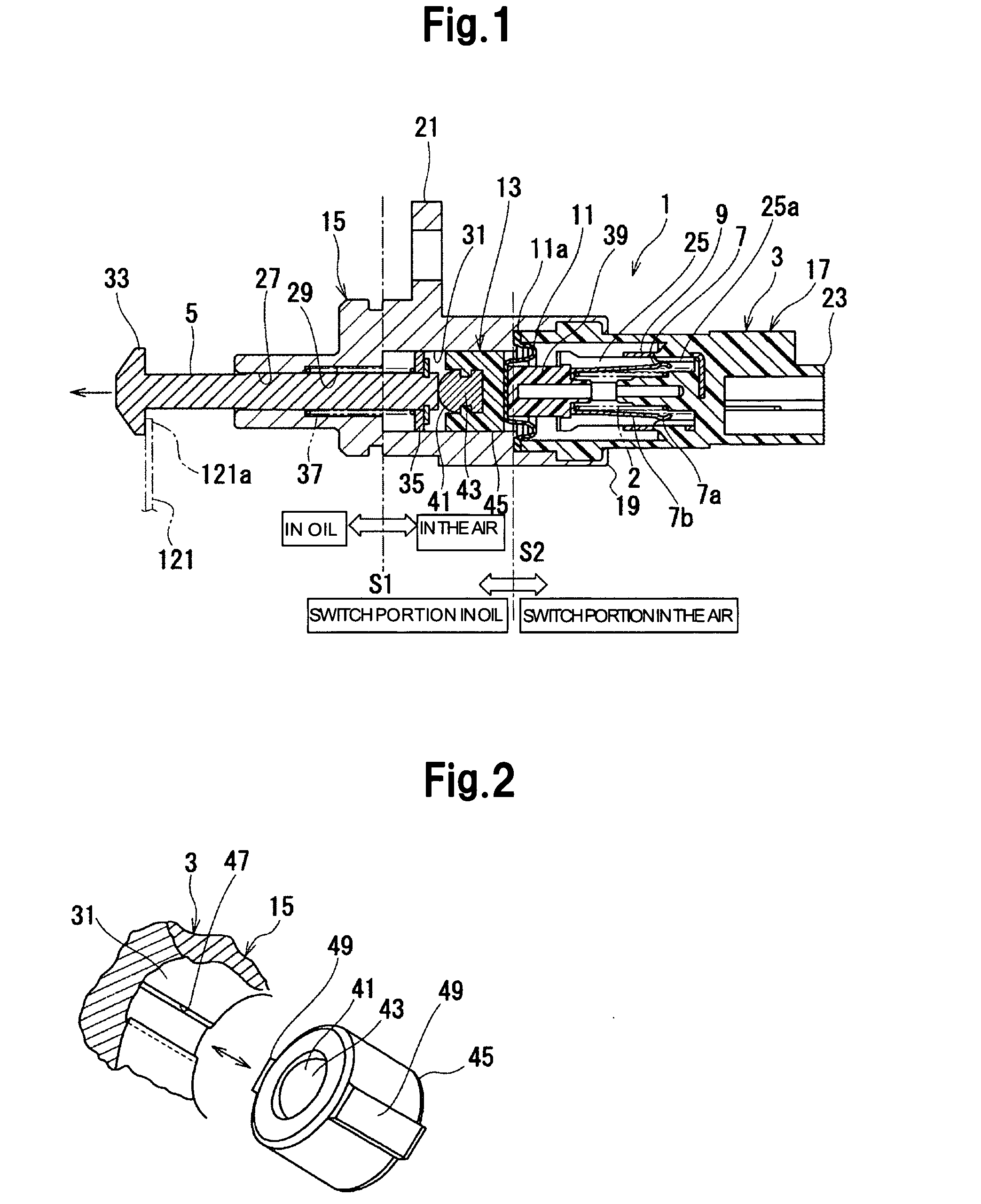
[0032]FIG. 1 is a cross section illustrating a switch apparatus according to an embodiment of the present invention. FIG. 2 is a perspective view illustrating a retention member and a part of a switch case.

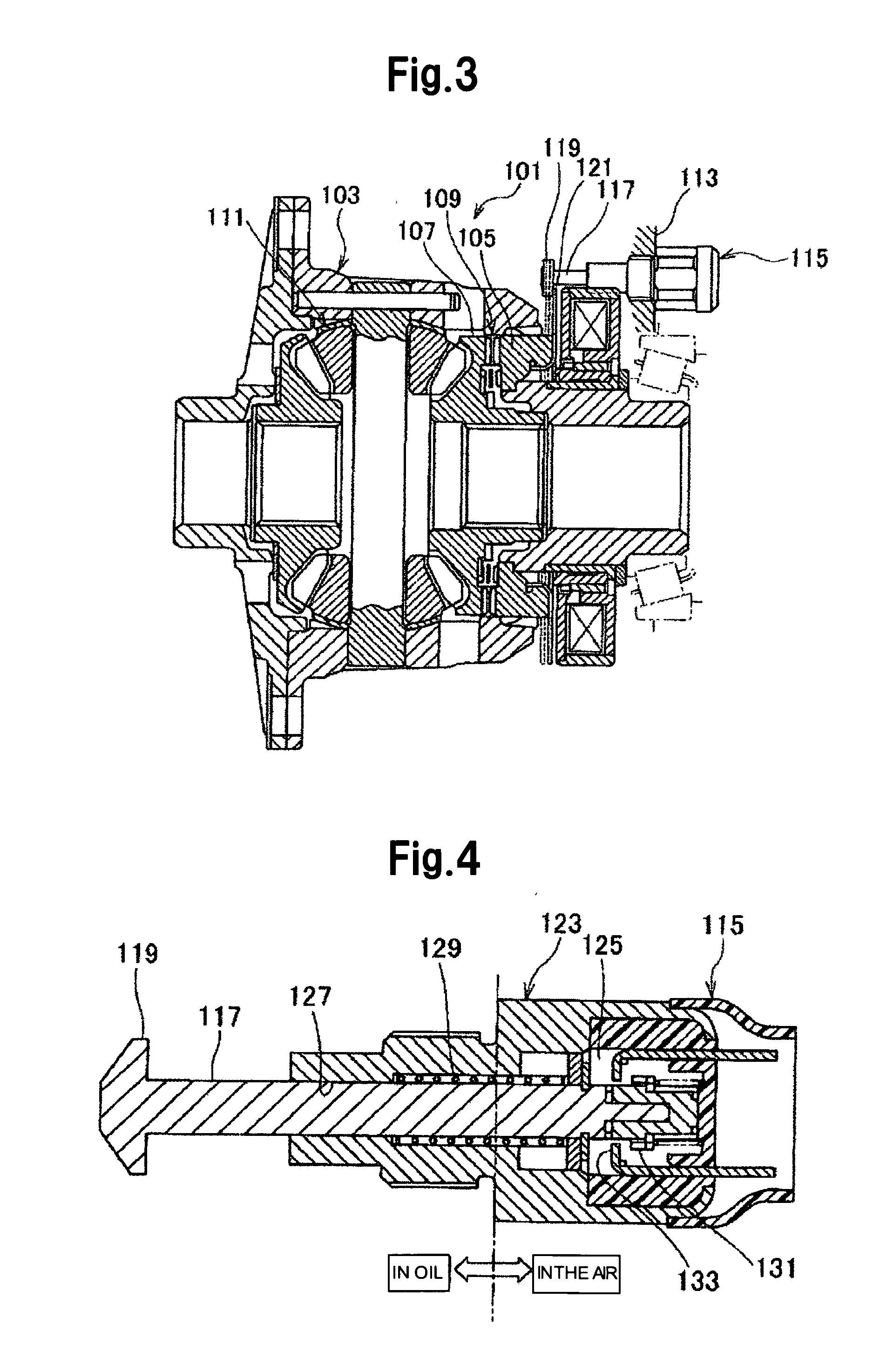
[0033]As illustrated in FIG. 1, a switch apparatus 1 used for detecting the differential lock state is attached to the differential carrier as illustrated in FIG. 3, for example.

[0034]The switch apparatus 1 includes a switch case 3, a rod 5, a movable contact 7, a fixed contact 9, a diaphragm 11 and a retention member 13.

[0035]The switch case 3 is provided with a metallic mounting portion 15 and a resinous electrical connecting portion 17. The switch case 3 is formed such that one portion 19 of the mounting portion 15 is staked to the electrical connecting portion 17.

[0036]At the outside of the switch case 3, a flange portion 21 for coupling is provided on the mounting portion 15 and a connector portion 23 is provided on the electrical connecting portion 17.

[0037]The switch case 3...


PUM


Abstract

The present invention aims at achieving the object of keeping a contact housing portion liquid tight sealed and to improve the durability of a switch apparatus. A switch apparatus according tothe present embodiment includes: a switch case 3 including a contact housing portion 25 therein and a shaft hole 27; a rod 5 whose outer flange portion 33 is capable of axially abutting on and engaging with a periphery portion 121a of a detecting plate; a first return spring 37 biasing the rod 5 in the direction opposite to protruding direction; a fixed contact 9 in the switch case 3 and a movable contact 7 which can reciprocally move between a position touching the fixed contact 9 and a non-touching position; a diaphragm 11 separating the shaft hole 27 from the contact housing portion 25 and being formed of rubber; a movable base 39 supporting the movable contact 7 and abutting on the diaphragm 11; a second return spring 2 bringing the movable contact 7 into contact with the fixed contact 9; and a retention member 13 interposed between the diaphragm 11 and the rod 5, including an abutting portion 41 for abutting on the rod 5, and axially movably, but not rotatably supported with respect to the switch case 3.

Description

BACKGROUND OF THE INVENTION[0001]1. Field of the Invention[0002]The present invention relates to a switch apparatus used for detecting a differential lock state in an automobile.[0003]2. Description of the Related Art[0004]Hitherto, there has been known a switch apparatus capable of detecting a locking state or an unlocking state of a differential apparatus, as illustrated in FIG. 3 (refer to Patent Document 1). FIG. 3 illustrates a cross section of a rear differential apparatus for an automobile.[0005]The rear differential apparatus 101 illustrated in FIG. 3 includes a locking device which locks a differential mechanism 111 such that a lock member 105 supported by a differential case 103 moves in the axial direction and engages a side gear 107 with a dog clutch 109.[0006]A differential lock state is detected by a switch apparatus 115 supported on the side of a differential carrier 113.[0007]The switch apparatus 115 is equipped with a rod 117 for detection. A flange 119 of the rod 1...

Claims


Application Information

Patent Timeline
Patent Type & Authority Applications(United States)
IPC IPC(8): H01H3/16
CPCH01H13/18H01H13/06
Inventor WATADA, TSUTOMUENDO, MASANORI
Owner NILES PARTS CO LTD
Why Eureka
Try Eureka