
Block Device for Nail Gun

Inactive Publication Date: 2009-05-21
DE POAN PNEUMATIC
View PDF25 Cites 20 Cited by
  • Summary
  • Abstract
  • Description
  • Claims
  • Application Information

AI Technical Summary

Benefits of technology

[0011]In the preferred embodiments, after the last nail in the nail cartridge is shot, a side of the brake member can move into the safety bar's moving up path so as to block the safety bar, which improves the accuracy and the reliability of blocking the shooting action of the nail gun. In addition, by disposing all the components such as the push member, the brake member, the fastener, the first elastic member and so on all inside the nail gun the contamination from outside dirt and dusts can be avoided. Moreover, after stopping the safety bar, the brake member can return to an original nail-pushing position along with the nail pusher during refilling of nails so as to release the safety bar and disable the shooting-blocked status of the nail gun, which overcomes the problem in the related art that the brake member rotates outwards so that the restoring force is insufficient to disable the shooting-blocked status of the nail gun.

Problems solved by technology

However, when the brake member rotates slopingly out of the nail cartridge as described above, the safety bar can only touch a sloping cross-section of the brake member, which may generate a sloping component force affecting the brake member.
As a result, the braking member may be easily pushed by the safety bar back to a non working position, which hence reduces the accuracy and the reliability of the blocking device in preventing the nail gun from shooting in the “no nail” status.
In addition, the spring board disposed on the outer wall of the nail cartridge is exposed outside and hence easy to be contaminated by outside dirt and dusts.
The spring board being configured for pushing the brake member is only a thin slice so that the elastic force it can provide to bring the brake member back to an original position after the brake member rotates outwards may be limited and even insufficient.
An elastic fatigue failure may happen to the spring board as well.

Method used


Image

  • Block Device for Nail Gun
  • Block Device for Nail Gun
  • Block Device for Nail Gun

Examples


Embodiment Construction

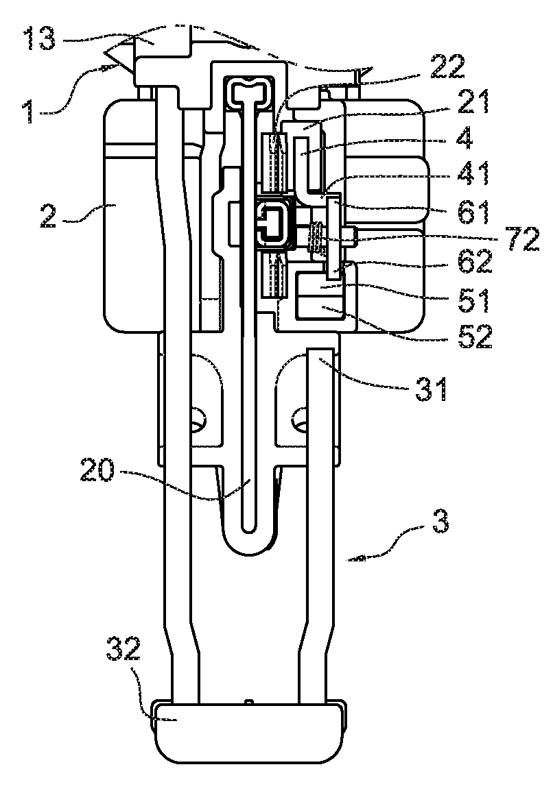
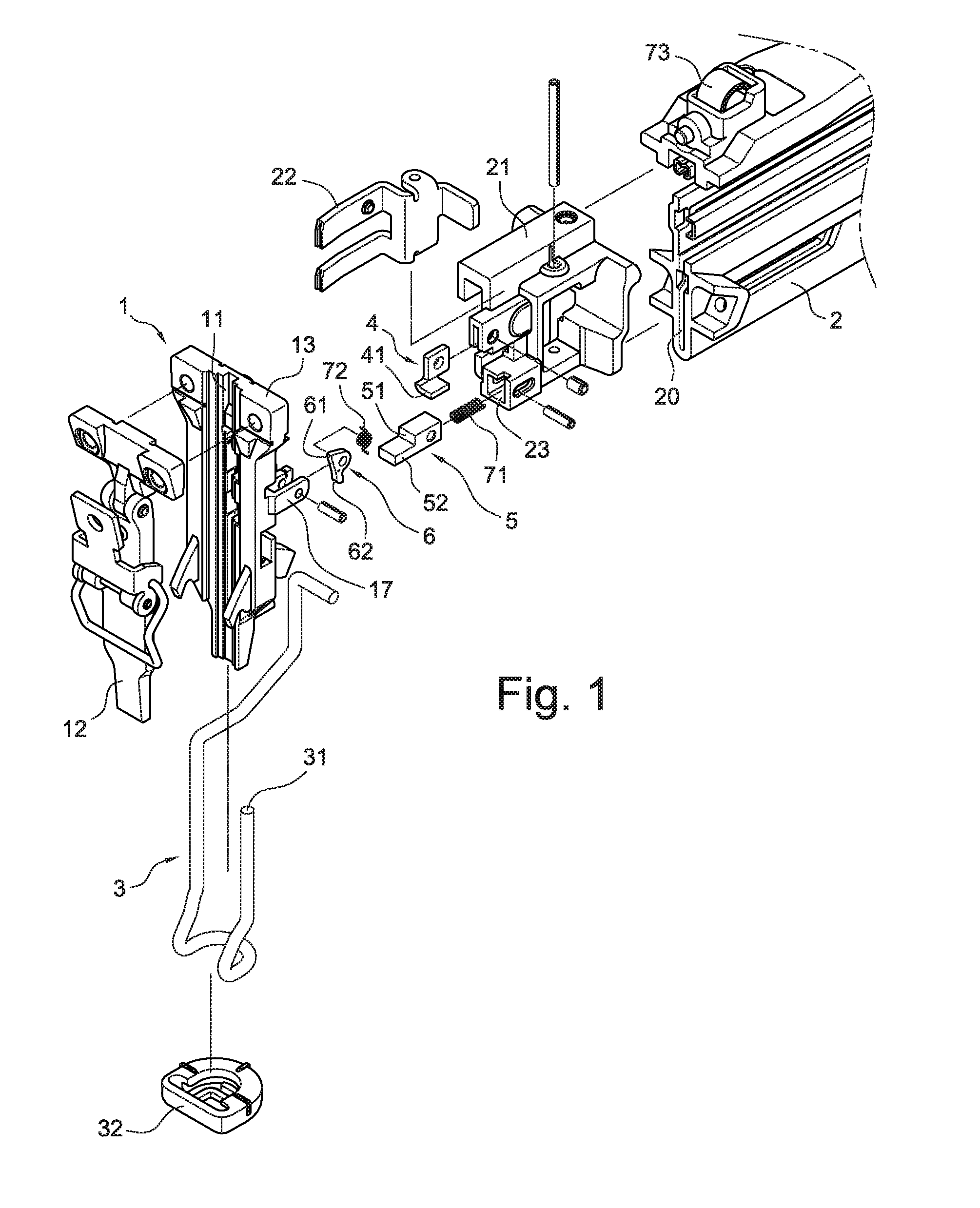
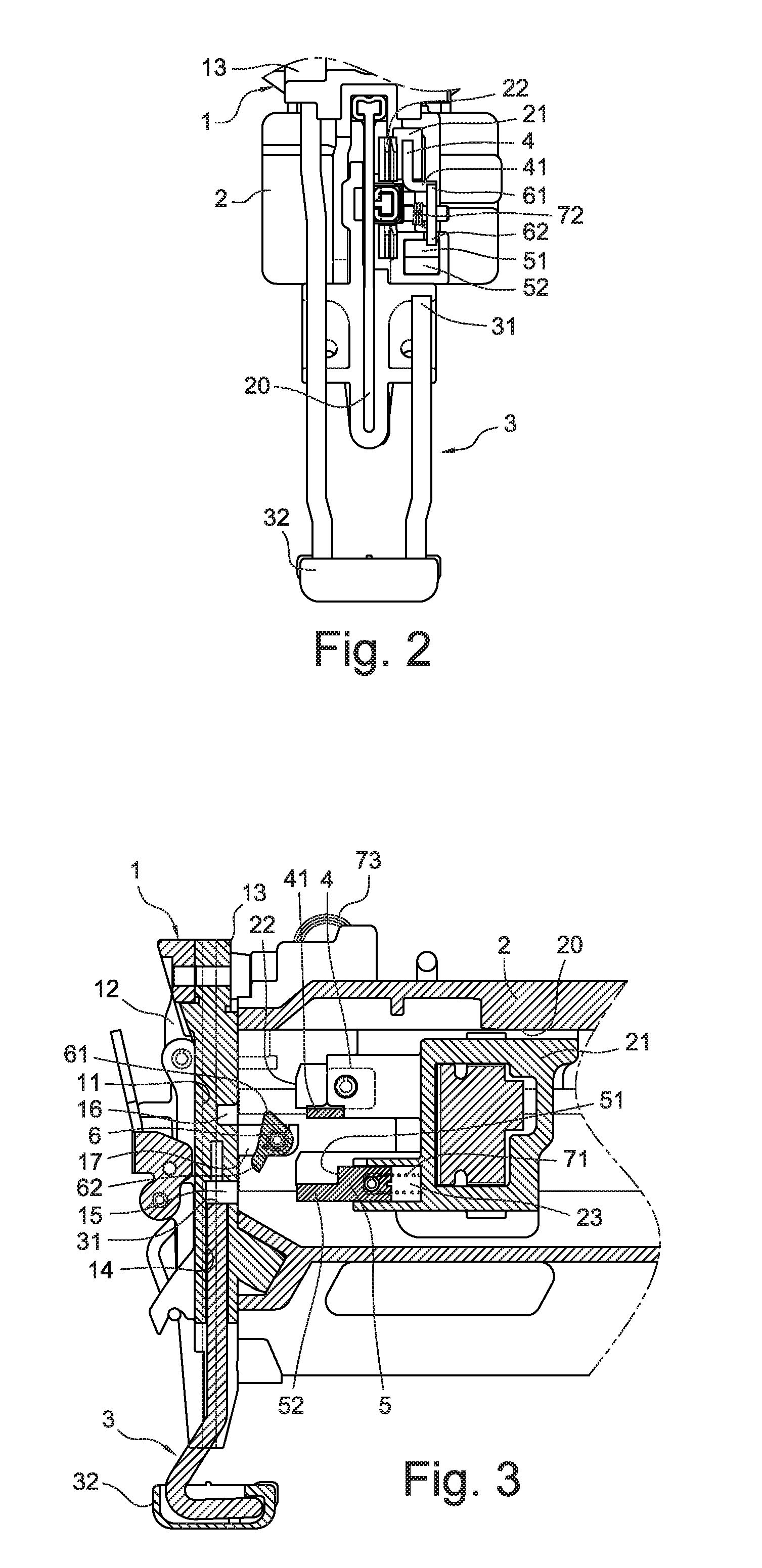
[0023]Referring to FIG. 1, FIG. 2 and FIG. 3, a blocking device for a nail gun in accordance with a preferred embodiment of the present invention is provided. The blocking device is installed on the nail gun, the nail gun having a nail groove base 1, a safety bar 3, and a nail cartridge 2. The blocking device includes:

[0024]a push member 4, disposed on a nail pusher 21 in the nail cartridge 2 and configured for moving toward the nail groove base 1 along with the nail pusher 21 pushing the multiple nails 8 in rows (as shown in FIG. 4 to FIG. 7);

[0025]a brake member 5, movably installed on the nail pusher 21 by a spring, and configured for moving toward the nail groove base 1 with the nail pusher 21 pushing the multiple nails 8 in rows; and

[0026]a rotational fastener 6, pivotably installed on the nail groove base 1 by a spring on a moving path of the push member 4 and the brake member 5, configured to be touched to rotate by the push member 4 when there are a small number of remaining...


PUM

PropertyMeasurementUnit
Forceaaaaaaaaaa

Abstract

A blocking device for a nail gun includes a push member disposed on a nail pusher in a nail cartridge of the nail gun for moving toward a nail groove base with the nail pusher, a brake member movably installed on the nail pusher for moving toward the nail groove base with the nail pusher, and a rotational fastener pivotably installed on the nail groove base on a moving path of the push member and the brake member. The fastener can be touched to rotate by the push member when there are a small number of remaining nails in the nail cartridge so as to prevent the brake member moving to a position where it blocks an upward movement of the safety bar, and can be released by the push member and rotate back to an original position when there is no remaining nail in the nail cartridge so as to release the brake member to move to a position where it blocks an upward movement of the safety bar and thereby a nail shooting action of the nail gun. The accuracy of the nail shooting blocking is improved.

Description

BACKGROUND OF THE INVENTION[0001]1. Field of the Invention[0002]The present invention relates to a blocking device for a nail gun for preventing a shooting action of the nail gun when there are no nails in the nail gun, and more particularly to a technology to detect whether there is any nail in the nail gun so as to hold or release a safety bar of the nail gun accordingly.[0003]2. Description of Related Art[0004]In most nail guns, there is generally a blocking device configured for automatically detecting for a “no nail” status when all nails, which are aligned in rows in a nail cartridge of the nail gun, are depleted during an operation of the nail gun and when such a status is detected disabling a trigger of the nail gun to drive a nail hitting bar to make a hitting movement so as to inform an operator to fill in nails to the nail gun.[0005]A relatively advanced technology, as disclosed by Taiwan patent M269156, provides a blocking device for a nail gun for preventing a shooting ...

Claims


Application Information

Patent Timeline
IPC IPC(8): B27F7/02
CPCB25C5/1665
Inventor YU, CHUNG HUNG
Owner DE POAN PNEUMATIC
Features
  • Generate Ideas
  • Intellectual Property
  • Life Sciences
  • Materials
  • Tech Scout
  • Unparalleled Data Quality
  • Higher Quality Content
  • 60% Fewer Hallucinations
Learn More