Methods and apparatus for sensing the internal temperature of an electrochemical device

Active Publication Date: 2014-12-18
HRL LAB
View PDF6 Cites 41 Cited by
  • Summary
  • Abstract
  • Description
  • Claims
  • Application Information

AI Technical Summary

Benefits of technology

[0045]In some embodiments, the temperature-sensing apparatus is a temperature sensor within a normal device operation temperature range selected from −30° C. to 60° C. (including any intermediate range of temperatures). In the

Problems solved by technology

On-line characterization of batteries or fuel cells in vehicles is difficult, due to very rough noisy environments.
An algorithm for a circuit model is relatively simple, meaning that simulation time is short and the computation cost is relatively low.
Conventionally, a thermocouple is used to measure the temperature of a device or structure, but very often, it is very difficult and troublesome to embed the thermocouples into a system, such as the case of an energy storage device (e.g., lithium-ion batteries).
However, t

Method used


Image

  • Methods and apparatus for sensing the internal temperature of an electrochemical device
  • Methods and apparatus for sensing the internal temperature of an electrochemical device
  • Methods and apparatus for sensing the internal temperature of an electrochemical device

Examples


example 1

Calibration of Impedance Spectrum as a Function of Temperature and State-of-Charge

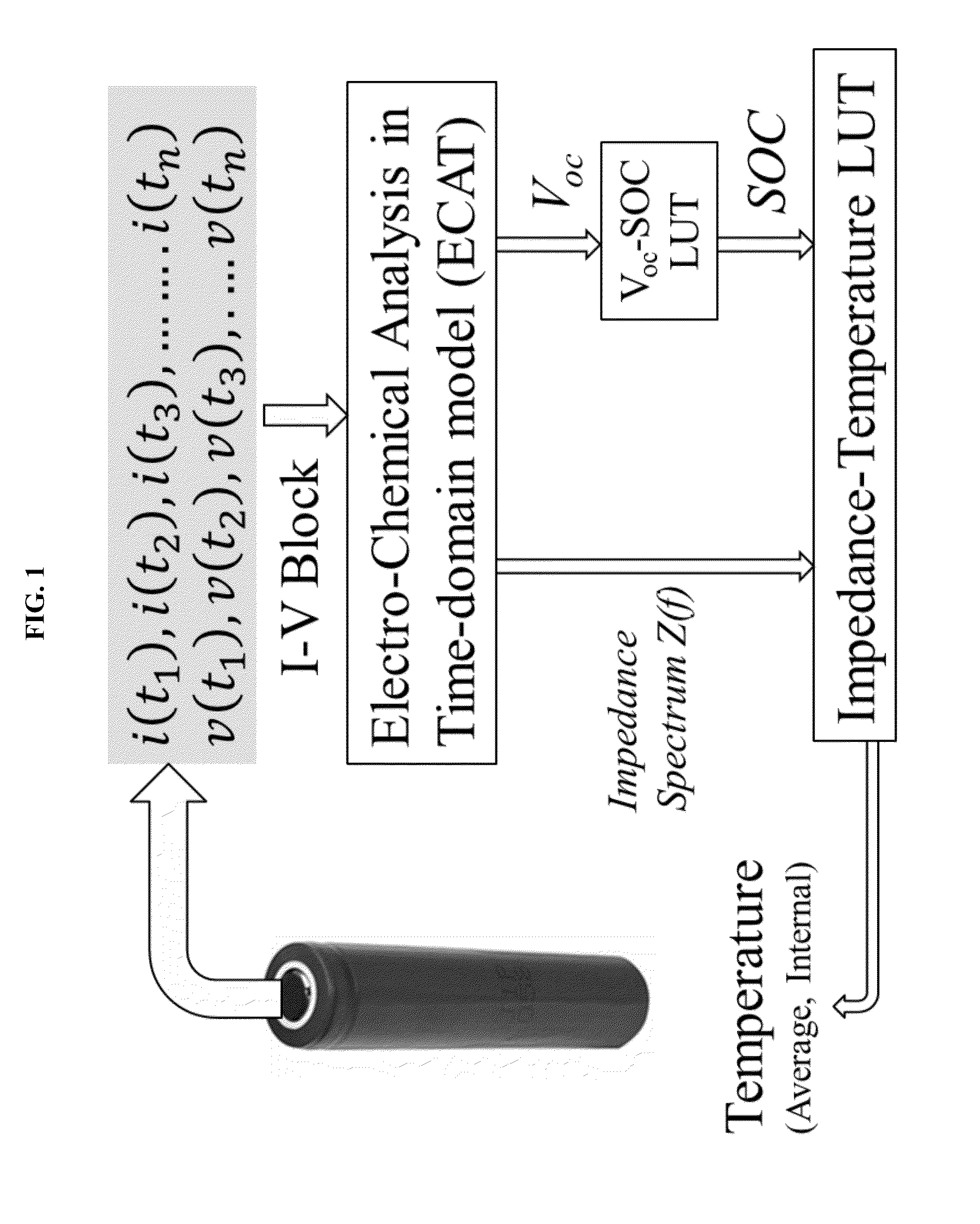
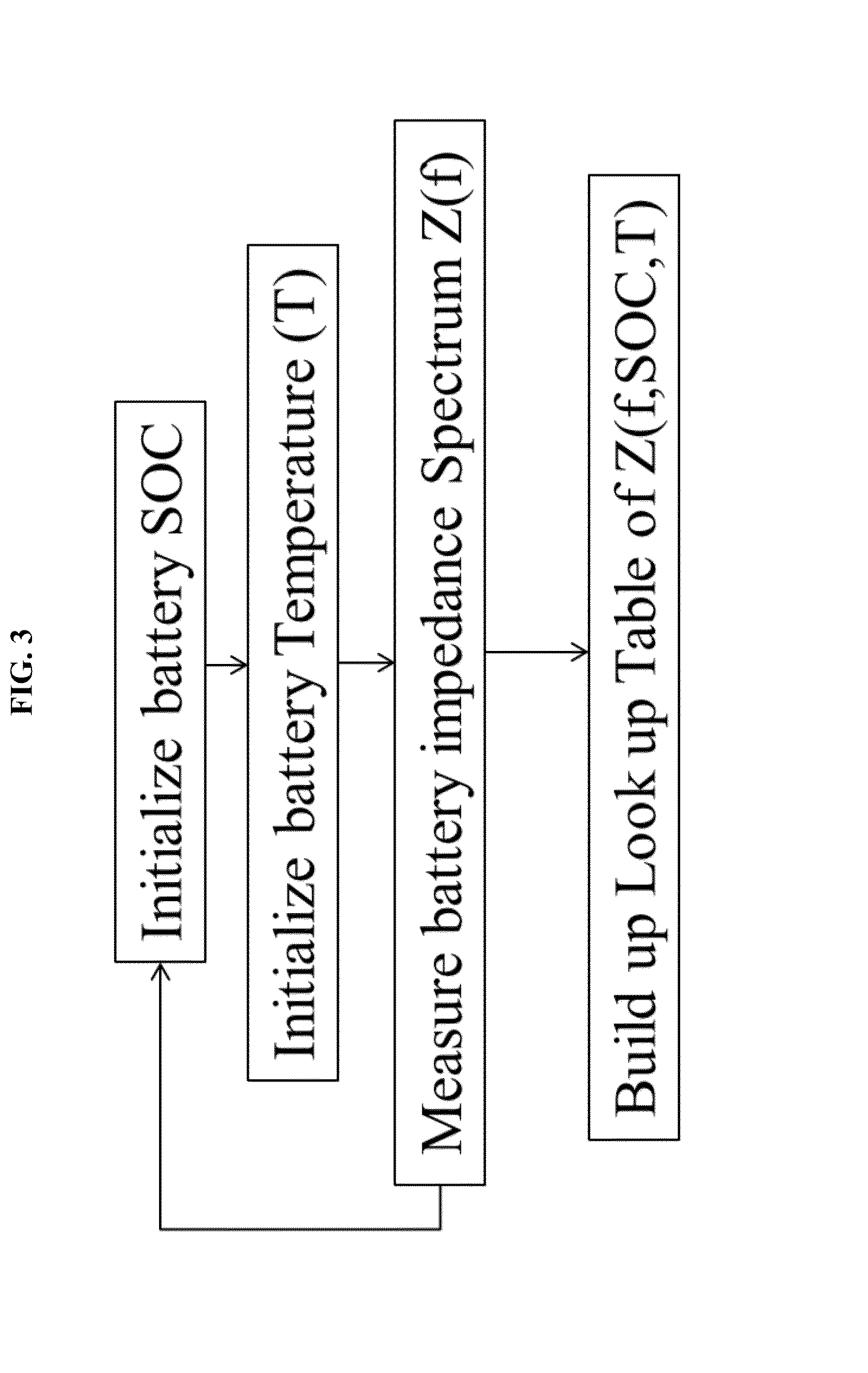
[0160]Battery impedance spectrum Z(f) is calibrated as the function of state-of-charge SOC and temperature T. A look-up table (LUT) of Z vs. Tat different SOC is then built with the calibration. The procedure for the calibration is as follows.

[0161]First, the voltage is floored to the minimum voltage of the battery, and the SOC is regarded as zero. In this Example 1, a Sanyo L333 NiMH cell is used with 1.5 Ah capacity and a voltage range is from 2.8 V to 4.2 V. We discharge the battery until it reaches 2.8 V. A Solartron 1260 is used for the current source. Next, the battery is charged to its 10% SOC, by charging the battery with a C / 5 current, i.e. 0.3 A, for half an hour.

[0162]Then the battery is placed into a thermal chamber and battery impedance spectrum is measured at different temperatures. The cell is attached with a thermocouple to the surface for temperature monitoring. An impedance spectromet...

example 2

Demonstration of Estimation of Internal Temperature of a Battery

[0164]This example demonstrated how to derive the battery inner temperature just based on the measured battery voltage and current data. First, the battery is initialized and the battery's open circuit voltage is measured with the voltage signal at initial time. Next, the battery is driven with a driving profile and the battery's current and voltage is sampled with a rate of 100 milliseconds (sampling period). The driving profile for this example is a double-pulse driving profile as described above.

[0165]The current and voltage data is input into a battery model. From the battery model, we obtain estimates of battery SOC and transfer impedance spectrum. Battery SOC is calculated based on the initial open circuit voltage and Coulomb counting. The battery impedance spectrum is calculated based on the impulse response model as described in this specification.

[0166]Then the battery inner temperature is estimated based on th...

example 3

Demonstration of the Relationship Between the Cell Impedance / Resistance, Temperature, and SOC

[0167]This information can be used to construct an empirical look-up table so that the temperature can be quickly determined once the impedance and SOC are known.

[0168]A 1.5 Ah, cylindrical commercially available Sanyo cell 18650 is composed of NiCoMn-based composite (LiMn1 / 3Ni1 / 3Co1 / 3+LiMn2O4) positive electrode and a graphite negative electrode. AC electrochemical impedance spectra (EIS) are acquired with a Solartron Electrochemical Interface 1260 coupled with a Solartron frequency response analyzer 1255. The EIS measurements are carried out in a frequency range between 0.01 to 100 kHz (0.01 to 1 Hz) and an AC amplitude of 0.5 mV.

[0169]FIG. 5 shows impedance spectra from the cell tested at different SOC (10%, 30%, 50%, 70%, and 90%) and various temperatures (10° C., 25° C., and 40° C.). Note that in FIG. 5, each temperature label applies to five curves of varying SOC, i.e. there are three ...


PUM


Abstract

The internal temperature of an electrochemical device may be probed without a thermocouple, infrared detector, or other auxiliary device to measure temperature. Some methods include exciting an electrochemical device with a driving profile; acquiring voltage and current data from the electrochemical device, in response to the driving profile; calculating an impulse response from the current and voltage data; calculating an impedance spectrum of the electrochemical device from the impulse response; calculating a state-of-charge of the electrochemical device; and then estimating internal temperature of the electrochemical device based on a temperature-impedance-state-of-charge relationship. The electrochemical device may be a battery, fuel cell, electrolytic cell, or capacitor, for example. The procedure is useful for on-line applications which benefit from real-time temperature sensing capabilities during operations. These methods may be readily implemented as part of a device management and safety system.

Description

PRIORITY DATA[0001]This non-provisional patent application claims priority to U.S. Provisional Patent Application No. 61 / 834,933, filed Jun. 14, 2013, and to U.S. Provisional Patent Application No. 61 / 834,906, filed Jun. 14, 2013, each of which is hereby incorporated by reference herein in its entirety.FIELD OF THE INVENTION[0002]The present invention generally relates to the real-time characterization of electrochemical devices, such as batteries and fuel cells, and in particular to internal temperature estimation in such devices.BACKGROUND OF THE INVENTION[0003]An electrochemical system is a system that either derives electrical energy from chemical reactions, or facilitates chemical reactions through the introduction of electrical energy. An electrochemical system generally includes a cathode, an anode, and an electrolyte, and is typically complex with multiple heterogeneous subsystems, multiple scales from nanometers to meters. Examples of these systems include fuel cells, batte...

Claims


Application Information

Patent Timeline
IPC IPC(8): G01K13/00G01R31/36
CPCG01R31/3624G01K13/00G01K7/427G01R31/374G01R31/389G01R31/3842G01R31/367G01R31/382H01M10/486Y02E60/10
Inventor WANG, JOHNWANG, SHUOQINSOUKIAZIAN, SOURENGRAETZ, JASON A.
Owner HRL LAB
Why Eureka
Try Eureka