
Method and system for monitoring motor temperature as well as method and system for controlling motor power

A technology of motor temperature and motor power, applied in the field of automotive power systems, can solve the problems of small power range, low system reliability and maintenance-free, and power changes are not smooth enough to achieve smooth power control, improve reliability and avoidance. The effect of maintainability, high accuracy and reliability

Inactive Publication Date: 2011-07-27
CHERY AUTOMOBILE CO LTD
View PDF6 Cites 42 Cited by
  • Summary
  • Abstract
  • Description
  • Claims
  • Application Information

AI Technical Summary

Problems solved by technology

However, the traditional motor temperature monitoring method is relatively simple, it only uses a temperature sensor to obtain the motor temperature, and does not judge whether the detection data of the temperature sensor is normal, resulting in low system reliability and maintenance-free
In addition, in the traditional motor power control, the motor power is simply limited according to the obtained motor temperature, for example, when the motor temperature exceeds a certain threshold, the maximum output power of the motor is directly limited to zero or 50% of the peak power, etc. With this power control method, the actual power range available for electric vehicles is relatively small, and since the motor power is directly limited to a specific percentage of the set power or peak power when the motor temperature exceeds the set value, the change in power It is not smooth enough, so that the actual maximum output power of the motor in a certain temperature range will be greater than the set power, so it cannot guarantee that it can output larger power while protecting the motor

Method used


Image

  • Method and system for monitoring motor temperature as well as method and system for controlling motor power
  • Method and system for monitoring motor temperature as well as method and system for controlling motor power
  • Method and system for monitoring motor temperature as well as method and system for controlling motor power

Examples


Embodiment Construction

[0029] In order for those skilled in the art to better understand the technical solution of the present invention, the motor temperature monitoring method and system and the motor power control method and system provided by the present invention will be described in detail below with reference to the accompanying drawings.

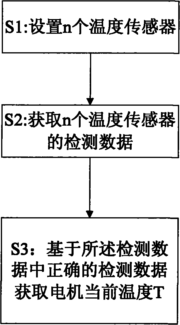
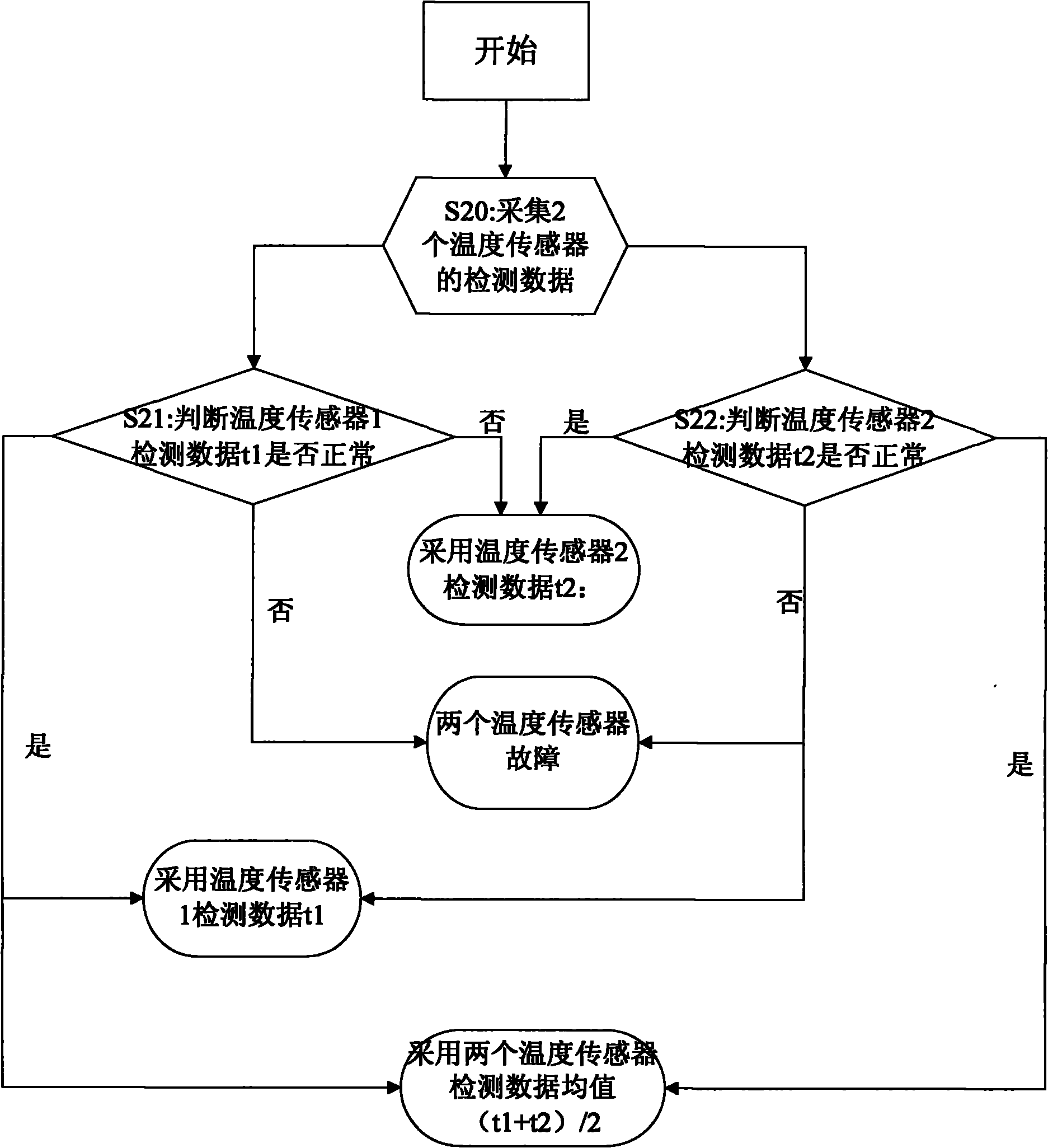
[0030] Such as figure 1 Shown is a flow chart of the motor temperature monitoring method of the present invention. In step S1, set n temperature sensors for detecting the current temperature T of the motor, where n≥2; in step S2, read the detection data of the n temperature sensors; in step S3, based on the n The current temperature T of the motor is obtained from the detection data of a temperature sensor that is working normally among the temperature sensors, where the temperature sensor includes: a temperature sensor, a thermocouple, and an infrared temperature sensor.

[0031] Wherein, since the current temperature T of the motor is obtained based on ...


PUM


Abstract

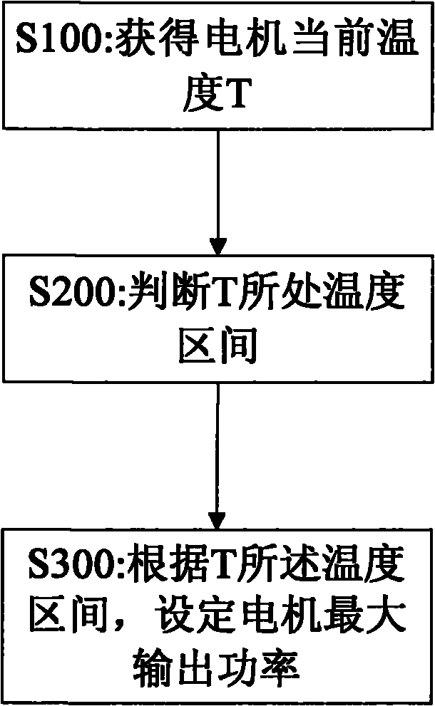
The invention discloses a method for monitoring motor temperature. The method comprises the following steps: arranging n temperature sensors for detecting the current temperature T of a motor, wherein, n is not less than 2; reading detection data from the n temperature sensors; and obtaining the current temperature T of the motor on the basis of the detection data from the temperature sensors which normally work in the n temperature sensors. The invention further provides a method for controlling motor power. The method comprises the following steps: obtaining the current temperature T of the motor by utilizing the method for monitoring motor temperature; judging temperature range of the current temperature T of the motor according to the current temperature T of the motor and a predetermined motor temperature range threshold; and setting the maximum output power of the motor according to the temperature range of the current temperature T of the motor. By utilizing the method for monitoring the motor temperature and the method for controlling the motor power, the current temperature of the motor can be effectively and reliably obtained, and reliably and maintenance-free performance of the motor can be improved.

Description

technical field [0001] The invention relates to an automobile power system, in particular to a motor temperature monitoring method and system of a pure electric vehicle and a motor power control method and system. Background technique [0002] At present, people pay more and more attention to the protection of the environment and the effective and rational use of energy. The electric drive system can achieve low energy consumption and zero emissions. Therefore, pure electric vehicles with high efficiency, energy saving and environmental protection have become one of the development trends of the automobile industry and have great market prospects. [0003] In the electric vehicle system, the motor drive system is limited by the installation space of the electric vehicle, and has strict requirements on its volume and size. The sine wave permanent magnet synchronous motor has significant advantages such as reliable operation, small size, light weight, low loss, high efficienc...

Claims


Application Information

Patent Timeline
IPC IPC(8): G01K7/04G01J5/00H02P6/00H02P29/60
Inventor 罗晓陈立冲王瑛宋波
Owner CHERY AUTOMOBILE CO LTD
Learn More