Connection Device for Medium Conduits

Active Publication Date: 2009-05-21
VOSS AUTOMOTIVE
View PDF8 Cites 34 Cited by
  • Summary
  • Abstract
  • Description
  • Claims
  • Application Information

AI Technical Summary

Benefits of technology

[0005]The object on which the present invention is based is to improve a connection device of the type mentioned, such that the assembly of the individuals parts is simplified and a si

Problems solved by technology

Although very simple manual release is possible here, the projecting actuation extensions o

Method used


Image

  • Connection Device for Medium Conduits
  • Connection Device for Medium Conduits
  • Connection Device for Medium Conduits

Examples


Example

[0034]In the various figures of the drawing, identical parts are always given the same reference symbols, and therefore any description of a part which may possibly occur only once with reference to a specific drawing figure also applies similarly to the other drawing figures in which the part with the corresponding reference numeral can likewise be seen.

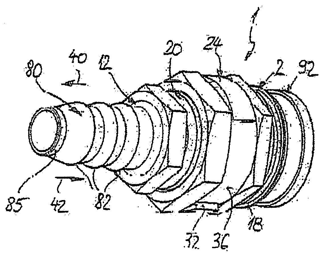
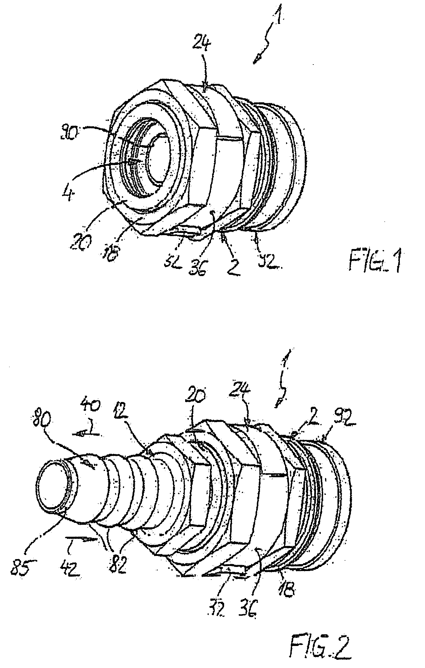
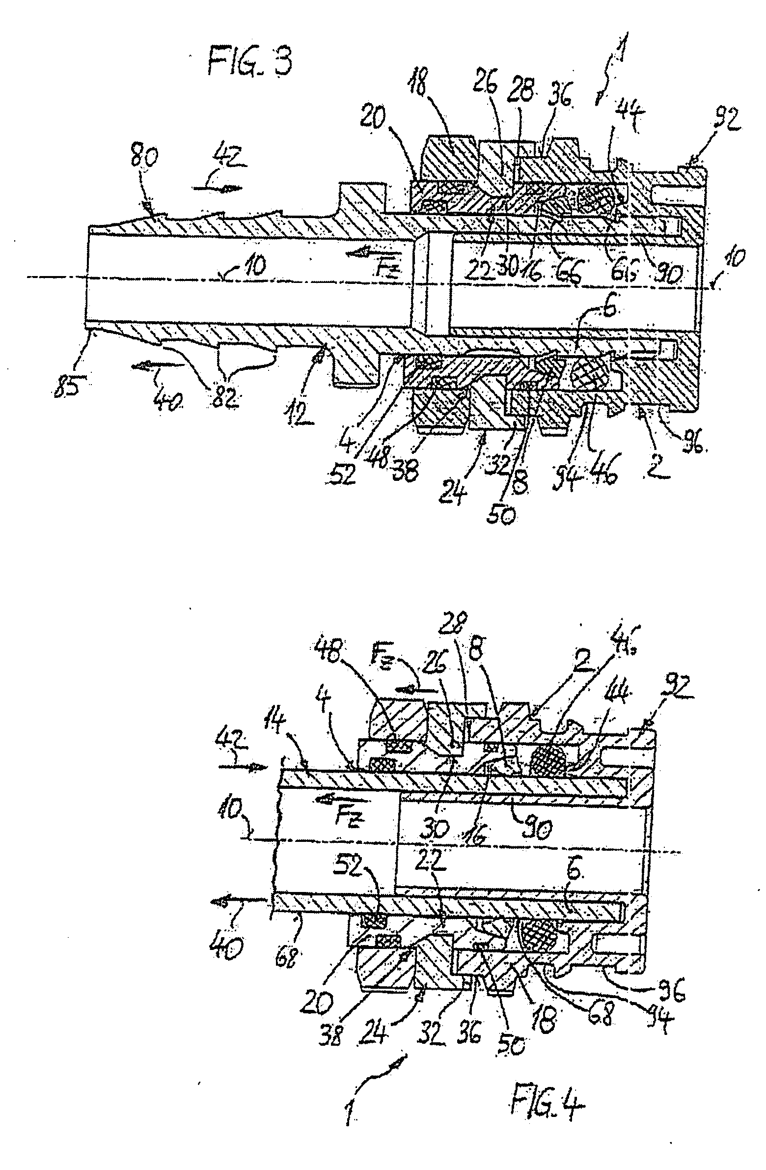
[0035]A connection device 1 according to the invention comprises a housing part 2 with (at least) one reception orifice 4, open on one side (toward the plug-in side), for axially plugging in an essentially hollow-cylindrical plug portion 6 and of a clamping ring 8, arranged in the housing part 2 or in the reception orifice 4 (see FIG. 1), for detaining the plug portion 6 plugged in axially, that is to say in the direction of a plug axis 10. According to FIGS. 2 and 3, the plug portion 6 may be an integral part of a separate form plug 12, via which a media line can be connected indirectly. According to FIG. 4, however, the plug porti...


PUM

PropertyMeasurementUnit
Angleaaaaaaaaaa
Angleaaaaaaaaaa
Diameteraaaaaaaaaa

Abstract

A connection device for the plug connection of at least one media line includes a housing part with at least one reception orifice for plugging in a plug portion connected or connectable to the at least one media line. The housing part includes a basic part and an insert part. The basic part is releasably connected with a form fit to the insert part via a latching connection. The latching connection holds the insert part releasably and is formed by a C-shaped spring clip which is seated on the outside of the basic part and engages with at least one latching extension radially through an orifice of the basic part into a circumferential latching groove of the insert part.

Description

CROSS REFERENCE TO RELATED APPLICATIONS[0001]The application claims priority to PCT / EP / 2006 / 062940 filed on Jun. 6, 2006 and German Utility Model DE 20 2005 009 018.2, filed Jun. 9, 2005.FIELD OF THE INVENTION[0002]The present invention relates to a connection device for the plug connection of at least one media line (pipeline or hose line for gases or liquids).BACKGROUND OF THE INVENTION[0003]A connection device of this type is known from EP 0 733 844 B1. In EP 0 733 844 B1, the insert part consists of a one-piece plastic molding which, for the purpose of the releasability of the plugged-in plug portion detained by the clamping ring against being pulled out and formed by one line end, has two elastic latching arms which engage radially with latching extensions into the basic part and into latching orifices formed there. Each latching arm has an actuation portion projecting outward from the basic part. Consequently, the insert part can be released from the basic part, so that the pl...

Claims


Application Information

Patent Timeline
IPC IPC(8): F16L35/00H01R43/00
CPCF16L37/088Y10T29/53222F16L37/144F16L37/0925F16L37/0885F16L37/0926
Inventor HAGEN, HARALDSUHR, ANDREASMITTERER, REINER
Owner VOSS AUTOMOTIVE
Why Eureka
Try Eureka