Marine lantern controlled by GPS signals

a technology of gps signals and marine lanterns, applied in the direction of electric lighting with batteries, lighting and heating equipment, instruments, etc., can solve the problems of reducing the solar energy collected by the solar cells for a temporary period, requiring considerable prior knowledge of the local, and reducing the solar energy collected by the solar cells. , to achieve the effect of optimizing the energy collection

Inactive Publication Date: 2009-05-21
AUTOMATIC POWER
View PDF10 Cites 91 Cited by
  • Summary
  • Abstract
  • Description
  • Claims
  • Application Information

AI Technical Summary

Benefits of technology

[0013]The present invention is a remotely adjustable lighting device configured to an operational mode customized for the geographic location of the device. The lighting device is powered by a battery provided with solar charging. The lighting device, under control of an integral controller, is turned off and on for an illumination period as a function of both local sunrise and sunset times determined by a combination of time and date information and GPS positioning. The luminosity of the lighting device is autonomously controlled as a function of battery charge and the determined required illumination period. The solar charging system is oriented by the controller to optimize its energy collection by periodical adjustments.

Problems solved by technology

Conventional warning lighting systems require considerable prior knowledge about the local conditions where any light system will be installed.
Obtaining and applying this information involves considerable effort and time.
Furthermore, conventional warning lighting systems have no means of adjusting to unusual temporary increases in cloudiness, which may markedly reduce the solar energy gathered by the solar cells for a temporary period.
This limitation necessitates that the solar panels and battery systems must be oversized for conventional lighting systems.
However, present day warning light devices are not suitable for universal applicability.

Method used


Image

  • Marine lantern controlled by GPS signals
  • Marine lantern controlled by GPS signals
  • Marine lantern controlled by GPS signals

Examples


first embodiment

of the Lighting System

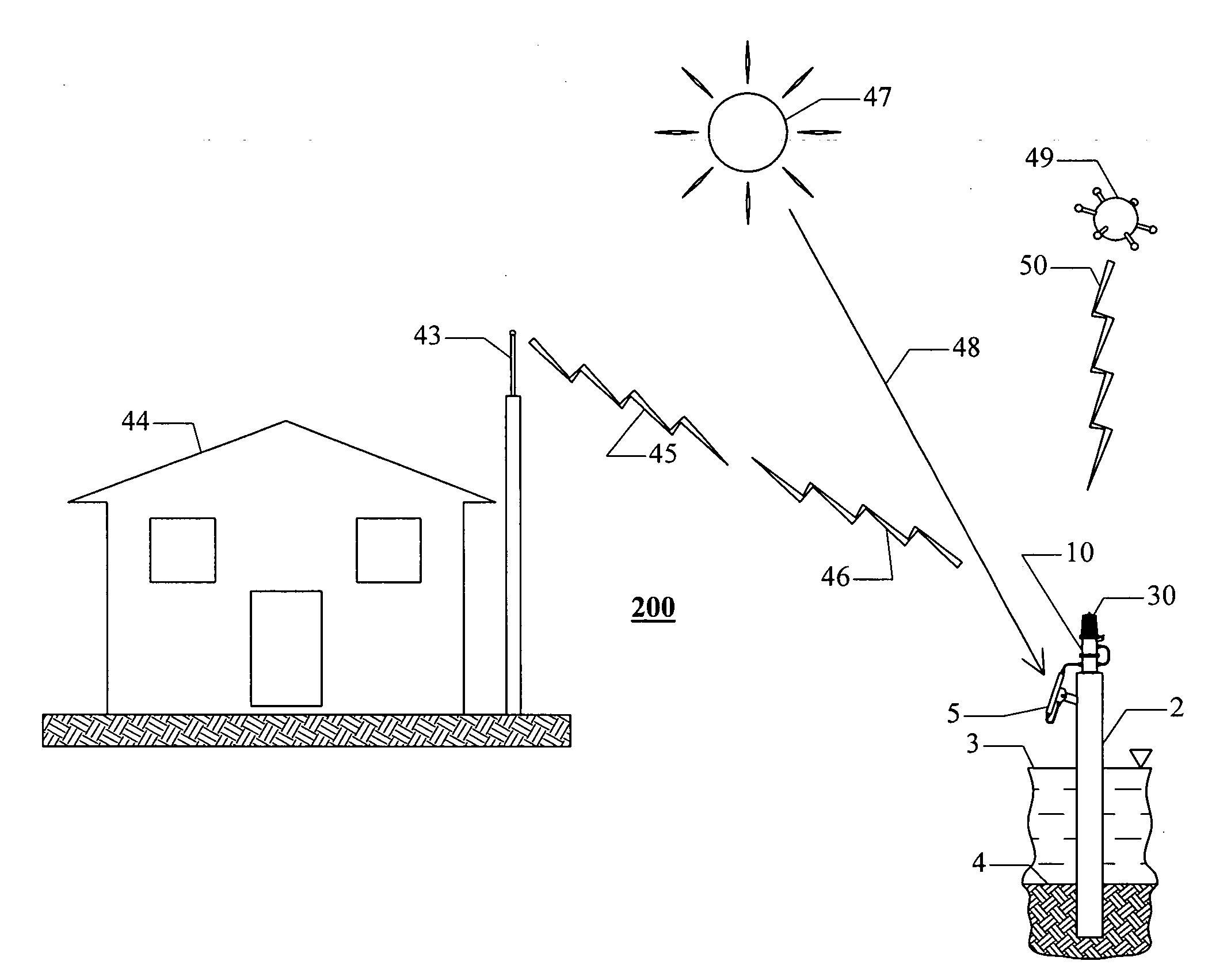
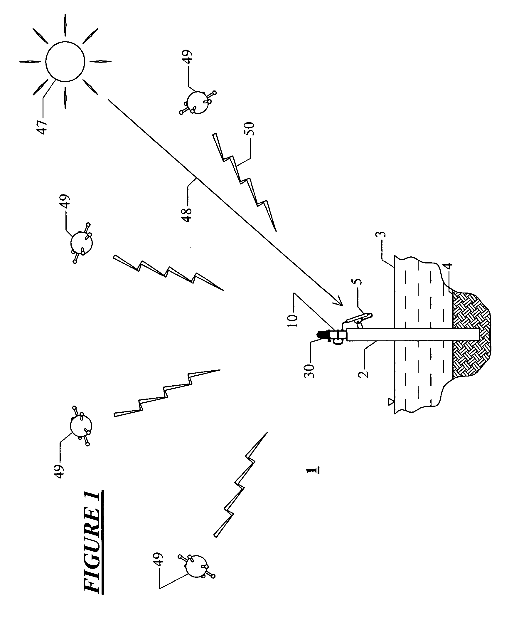
[0035]FIG. 1 shows a first embodiment of the lighting system 1 which includes the lighting device 10 of the present invention, wherein by way of example the lighting device is located on a vertical offshore piling structure 2 which is surrounded by water 3 and embedded in the seabed 4. The lighting device 10, shown in more detail in FIGS. 3 and 4, is attached rigidly to the upper end of the piling 2 sufficiently far above the surface of the water 3 that it is above splashing from passing wave crests at high tide during storms. Alternatively, the lighting device 10 can be positioned on a variety of other types of structures.

[0036]The electrical power necessary to operate the lighting device 10 is provided by a solar collector panel 5, which is able to collect and convert solar energy to electricity. Solar collector 5 is used to charge a battery or batteries 41 (shown in FIG. 5) in a battery case 6 integrally mounted with the lighting device. The collectors of th...

second embodiment 200

of Lighting System

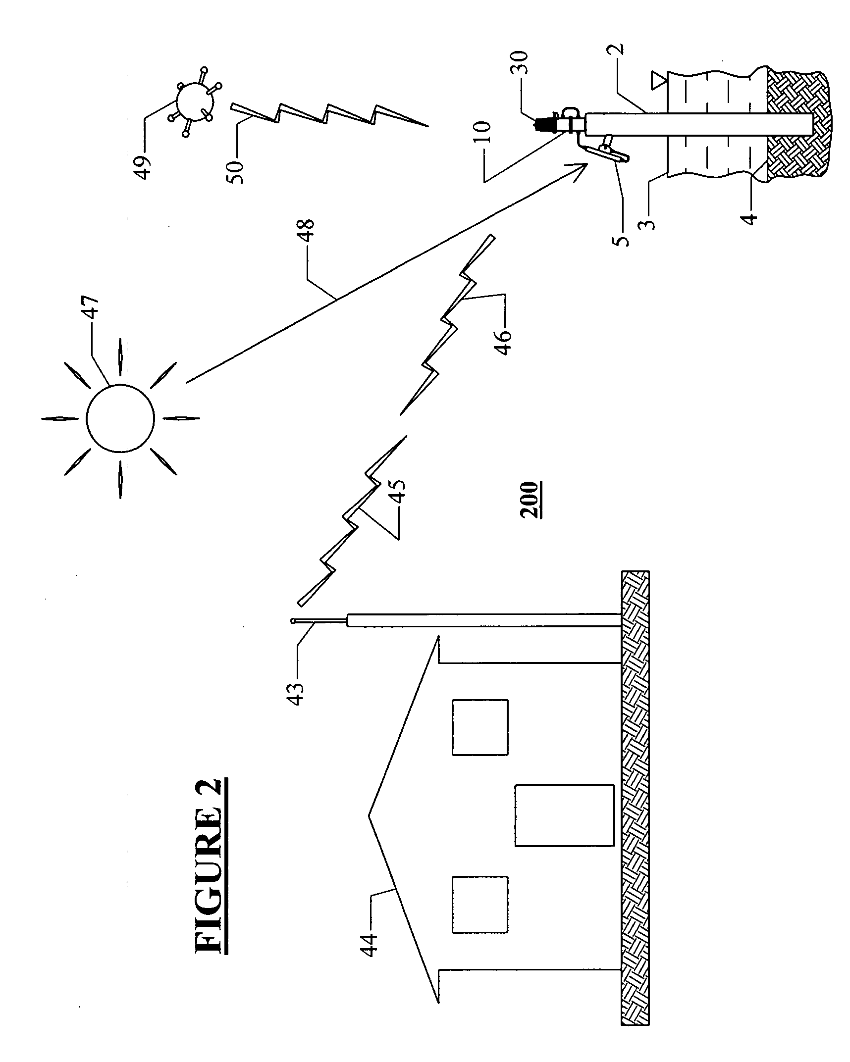
[0066]FIG. 2 shows a second embodiment 200 of the lighting system which includes the lighting device 10 of the present invention using a different controller assembly 240. As seen in FIG. 2, lighting system 200 externally uses the same basic arrangement as the first embodiment lighting system 1, but with the addition of means for interacting by two-way radio transmissions with a remote base station 44. By way of example, the remote base station 44 is shore based and has transceiving radio antenna 43 which is able to transmit radio signals 45 for reception by the controller assembly 240 of the lighting system 200. Additionally, the controller assembly 240 for the lighting device 10 is able to transmit outgoing radio signals 46 for reception by the antenna 43 of the base station 44.

[0067]Referring to FIG. 7, the interrelationship of the functional components of the controller assembly 240 of the lighting device 10 of the lighting system embodiment 200 may be seen sch...


PUM


Abstract

A remotely adjustable lighting device configured to an operational mode customized for the geographic location of the device. The lighting device is powered by a battery provided with solar charging. The lighting device, under control of an integral controller, is turned off and on for an illumination period as a function of both local sunrise and sunset times determined by a combination of time and date information and GPS positioning. The luminosity of the lighting device is autonomously controlled as a function of battery charge and the determined required illumination period. The solar charging system is oriented by the controller to optimize its energy collection by periodical adjustments.

Description

CROSS REFERENCE TO RELATED APPLICATIONS[0001]This application claims priority to pending U.S. Patent Application Ser. No. 60 / 850,783 (Attorney Docket Number APWR-P006V), filed Oct. 11, 2006 by inventors Alan Trojanowski and Gregory Lei Fan and entitled “Marine Lantern Controlled by GPS Signals.”BACKGROUND OF THE INVENTION[0002]1. Field of the Invention[0003]The present invention relates generally to a remotely adjustable lighting device powered by a rechargable battery provided with solar charging. More particularly, the invention relates to a remotely adjustable lighting device that is turned on and off for an illumination period as a function of local sunrise and sunset times determined by a combination of time and date information and GPS positioning.[0004]2. Description of the Related Art[0005]Reliable warning lights are critical for the safety of marine and aircraft vessels to prevent accidental collisions with fixed structures, such as offshore platforms, radio towers, high br...

Claims


Application Information

Patent Timeline
Patent Type & Authority Applications(United States)
IPC IPC(8): F21L4/00
CPCB63B51/02F21V23/0435Y02B20/42H05B37/0272H05B37/0281F21W2111/047H05B47/16H05B47/19Y02B20/40
Inventor FAN, GREGORY LEITROJANOWSKI, ALAN
Owner AUTOMATIC POWER
Why Eureka
Try Eureka