
Method for transmitting up link control signal in mobile communication system

a mobile communication system and control signal technology, applied in power management, synchronisation arrangement, wireless commuication services, etc., can solve the problem of difficult to apply a conventional method for transmitting control signals, and achieve the effect of maximising the use of limited radio resources

Active Publication Date: 2009-05-21
ELECTRONICS & TELECOMM RES INST
View PDF6 Cites 65 Cited by
  • Summary
  • Abstract
  • Description
  • Claims
  • Application Information

AI Technical Summary

Benefits of technology

[0009]According to an embodiment of the present invention, the utilization of limited radio resources can be maximized by efficiently forming uplink control information to be transmitted through a downlink from a base station to a terminal in a packet based mobile communication system and transmitting the uplink control information with minimum radio resources occupied.

Problems solved by technology

However, it is difficult to apply a conventional method for transmitting a control signal using the dedicated channel to a long term evolution (LTE) system that is a packet based system introduced for providing various packet services.

Method used


Image

  • Method for transmitting up link control signal in mobile communication system
  • Method for transmitting up link control signal in mobile communication system
  • Method for transmitting up link control signal in mobile communication system

Examples


Embodiment Construction

[0015]The advantages, features and aspects of the invention will become apparent from the following description of the embodiments with reference to the accompanying drawings, which is set forth hereinafter.

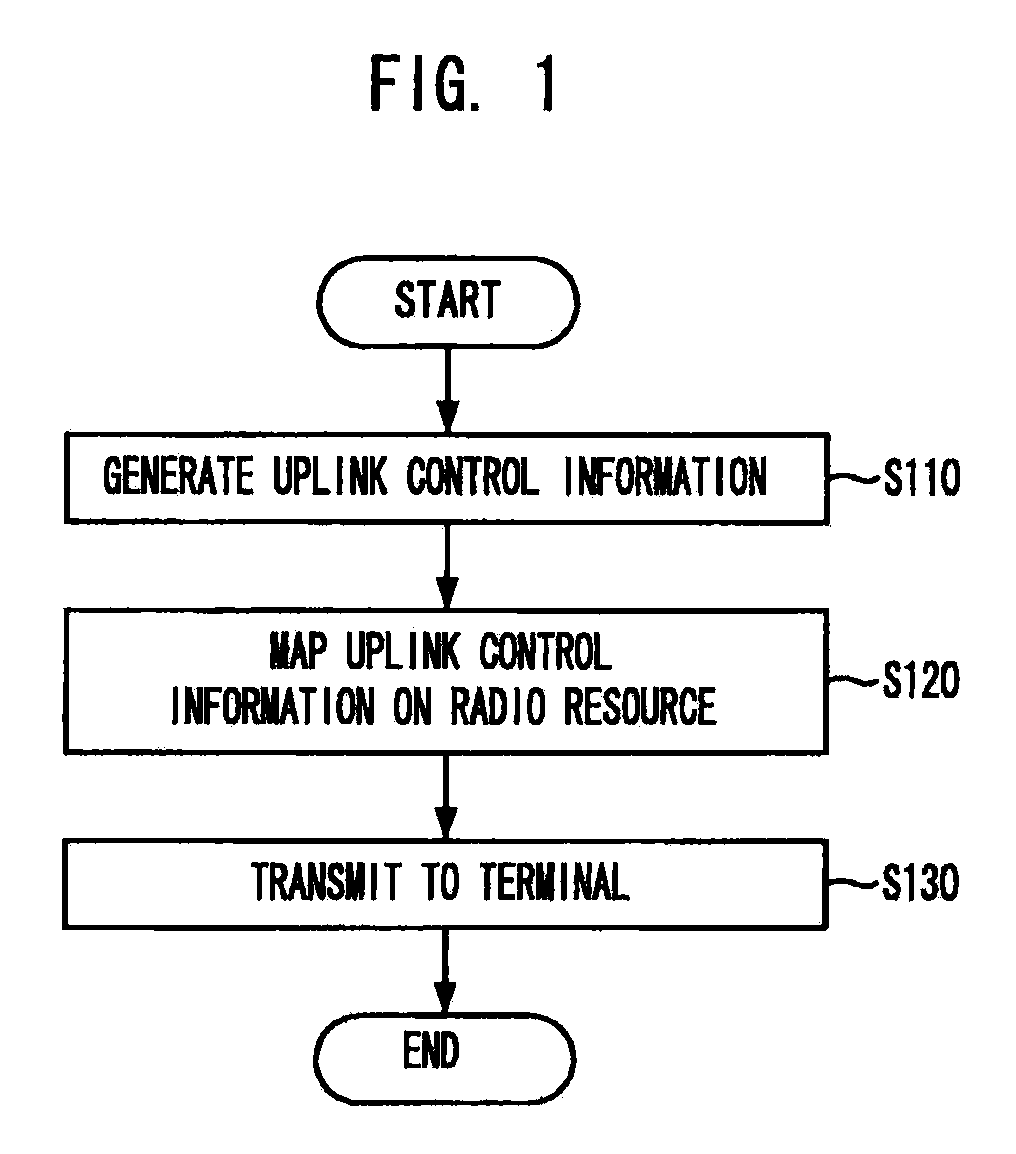
[0016]FIG. 1 is a flowchart illustrating a method for transmitting uplink control information in a mobile communication system in accordance with an embodiment of the present invention.

[0017]At first, a base station generates uplink control information to transmit to a terminal at step S110.

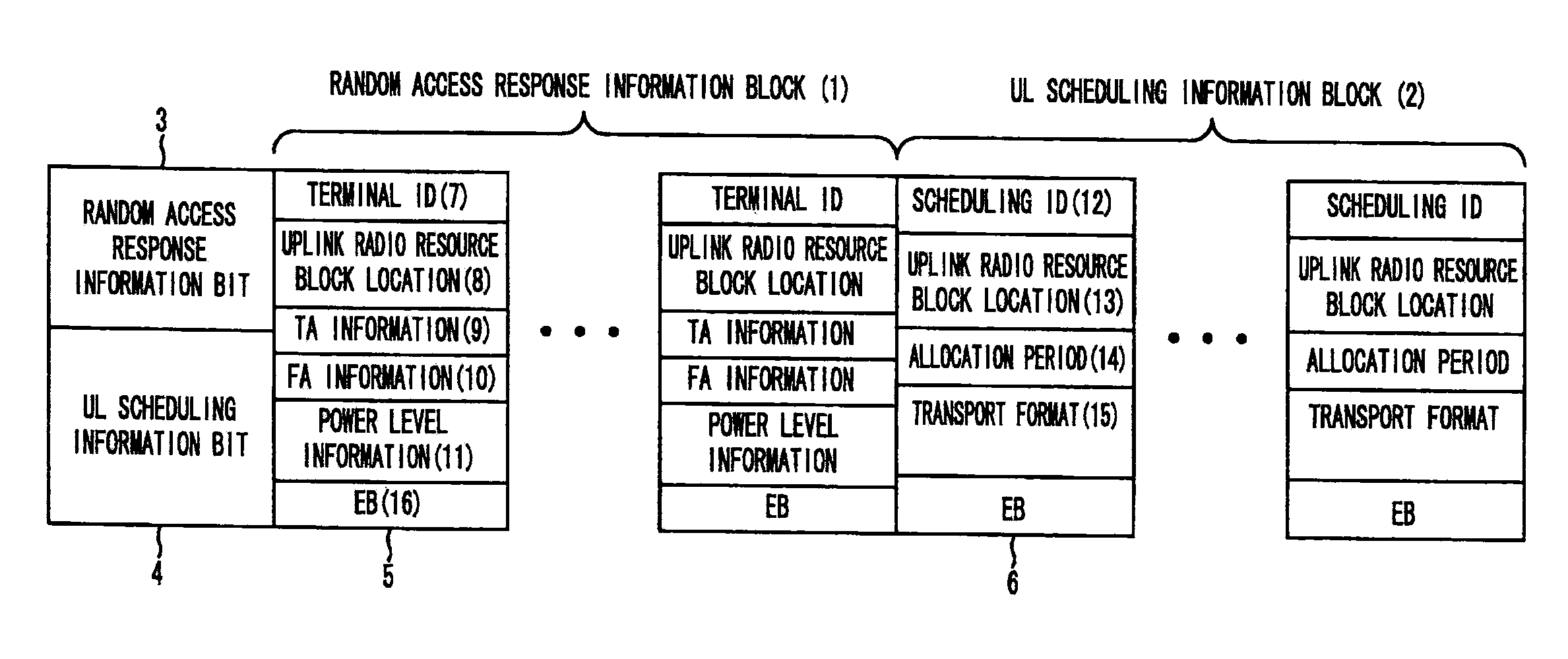
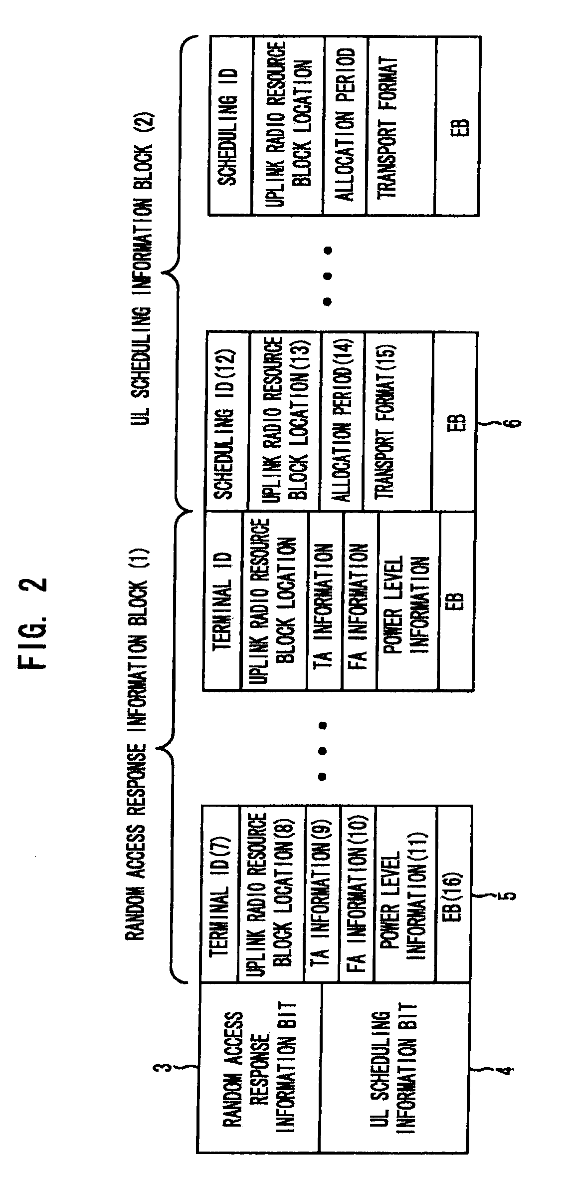
[0018]The uplink control information may include at least one among uplink scheduling information, random access response information, and response information for sustaining the uplink synchronization of a physical layer, which are required in a system based on Orthogonal Frequency Division Multiple Access (OFDMA) or Single Carrier—Frequency Division Multiple Access (SC-FDMA) technology. For example, the uplink control information may include both of uplink scheduling information and uplink r...


PUM


Abstract

The present invention relates to a method for transmitting uplink control information in a mobile communication system; and, more particularly, to a method for effectively forming uplink control information transmitted through a downlink from a base station to a terminal in a mobile communication system for providing a packet service and transmitting the uplink control information with minimum radio resources occupied. The method includes the steps of generating uplink control information; allocating the uplink control information to a downlink-shared radio resource for packet data transmission based on downlink scheduling information; and transmitting the radio resource to a terminal. The present invention is applied to a mobile communication system.

Description

TECHNICAL FIELD[0001]The present invention relates to a method for transmitting uplink control information in a mobile communication system; and, more particularly, to a method for effectively forming uplink control information transmitted through a downlink from a base station to a user terminal in mobile communication systems for providing a packet service and transmitting the uplink control information with minimum radio resources occupied.BACKGROUND ART[0002]A conventional mobile communication system is a circuit based system that enables a base station to transmit a control signal to a user terminal using a downlink-dedicated channel. However, it is difficult to apply a conventional method for transmitting a control signal using the dedicated channel to a long term evolution (LTE) system that is a packet based system introduced for providing various packet services. Currently, the related standardization processes of the LTE system have been in progress.[0003]Unlike the circuit...

Claims


Application Information

Patent Timeline
IPC IPC(8): H04W72/04
CPCH04L1/0025H04L1/0027H04L5/0007H04W74/0833H04W72/121H04W72/1273H04W74/006H04L27/2613H04W72/12H04W56/0005H04W72/23H04W8/24H04W56/0045H04W52/54
Inventor KIM, JAE-HEUNGKO, YOUNG-JOLEE, KYOUNG-SEOKKIM, JUNG-IMJUNG, SOO-JUNG
Owner ELECTRONICS & TELECOMM RES INST
Learn More