
Filtered photosensors and photo control devices including the same and methods for forming the same

Inactive Publication Date: 2009-05-28
TE CONNECTIVITY CORP
View PDF7 Cites 3 Cited by
  • Summary
  • Abstract
  • Description
  • Claims
  • Application Information

AI Technical Summary

Benefits of technology

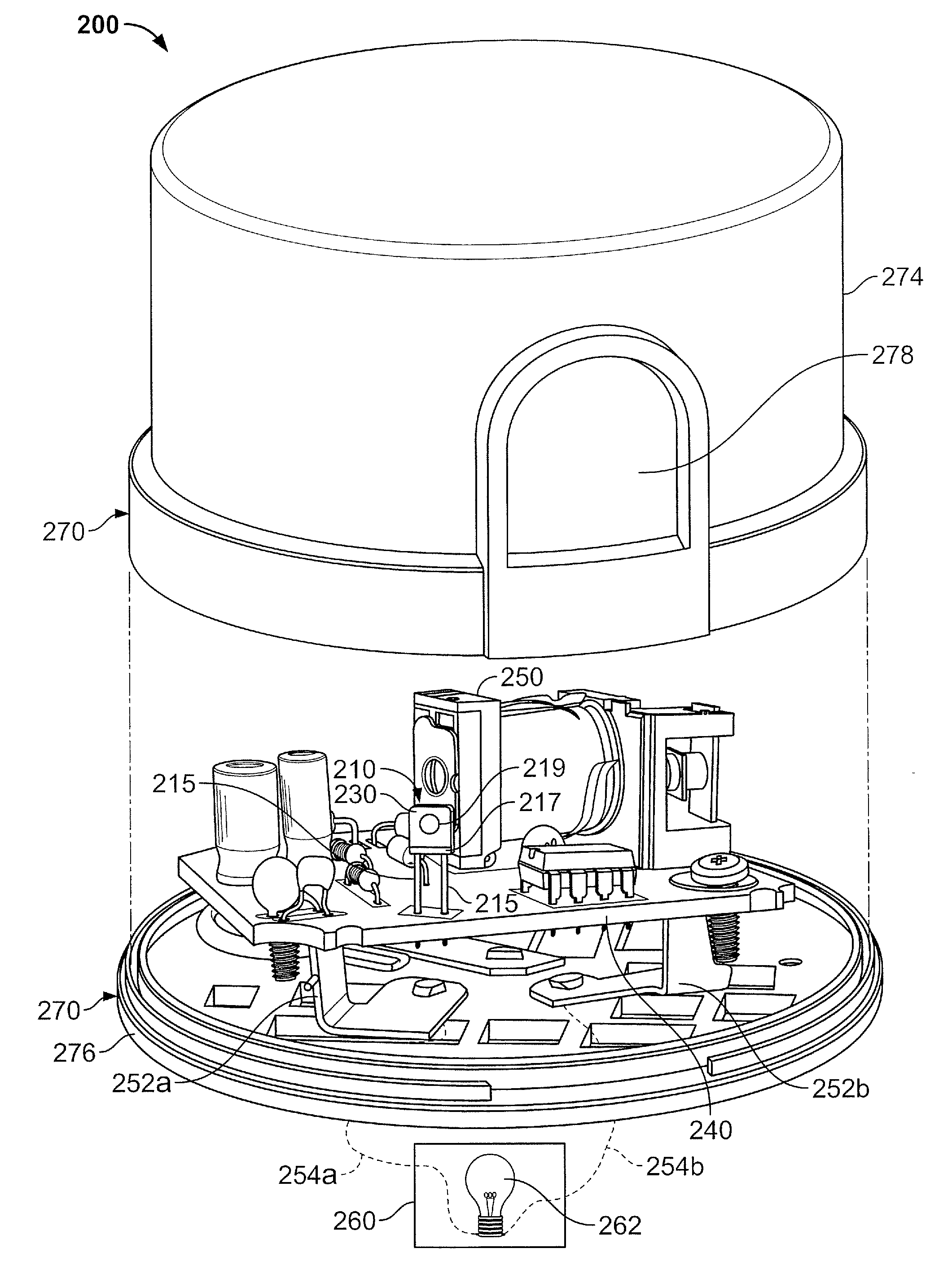
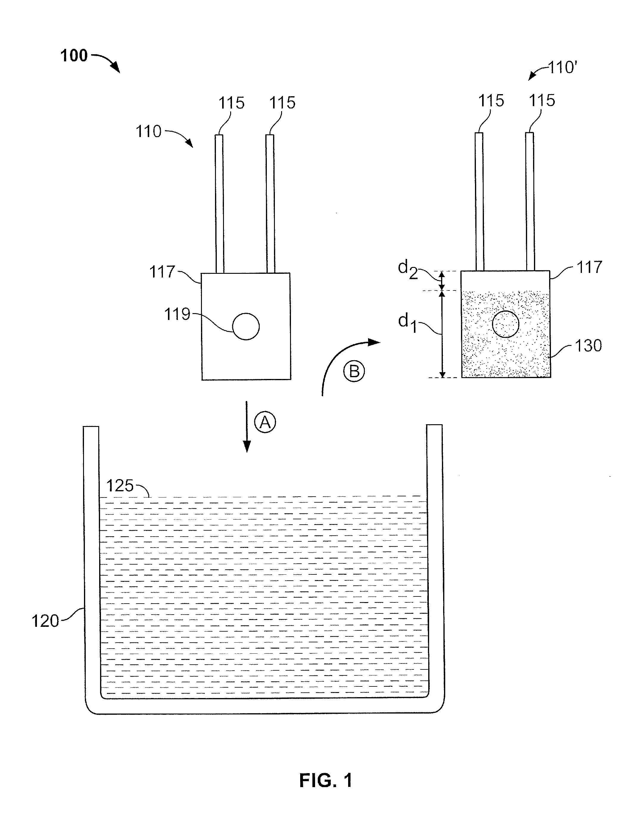
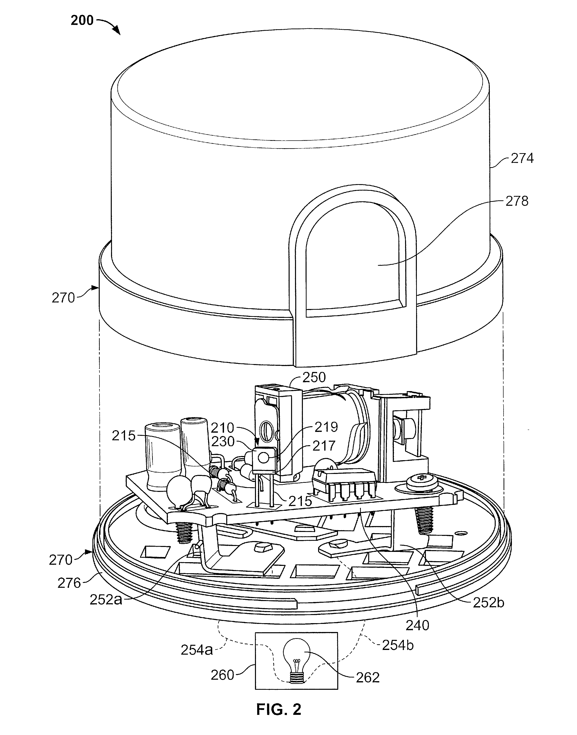
[0006]In further embodiments, methods of fabricating a photo control device including a filtered photosensor include providing a photosensor and an infrared blocking ink. The infrared blocking ink is printed on the photosensor. The printed photosensor is mounted on a circuit board. The circuit board, including the photosensor, is positioned in a housing of the photo control device with the photosensor positioned to receive light passing through the housing. The circuit board further includes a relay that is activated by the photosensor.
[0007]In other embodiments, positioning the circuit board including the photosensor in a housing of the photo control device is followed by mounting the photo control device to a lighting fixture. The photo control device is electrically coupled to a light source of the lighting fixture to control activation of the light source response a level of light detected by the photosensor.
[0008]In yet further embodiments, photo control devices

Problems solved by technology

Thus, photo controls manufactured with such photosensors may be sensitive to infrared electromagnetic radiation and the presence of infrared electromagnetic radiation may cause undesired operation of a photo control.

Method used


Image

  • Filtered photosensors and photo control devices including the same and methods for forming the same
  • Filtered photosensors and photo control devices including the same and methods for forming the same
  • Filtered photosensors and photo control devices including the same and methods for forming the same

Examples


Embodiment Construction

[0014]The present invention now will be described more fully hereinafter with reference to the accompanying drawings, in which illustrative embodiments of the invention are shown. In the drawings, the relative sizes of regions or features may be exaggerated for clarity. This invention may, however, be embodied in many different forms and should not be construed as limited to the embodiments set forth herein; rather, these embodiments are provided so that this disclosure will be thorough and complete, and will fully convey the scope of the invention to those skilled in the art.

[0015]It will be understood that, although the terms first, second, etc. may be used herein to describe various elements, components, regions, layers and / or sections, these elements, components, regions, layers and / or sections should not be limited by these terms. These terms are only used to distinguish one element, component, region, layer or section from another region, layer or section. Thus, a first elemen...


PUM


Abstract

Methods of forming a filtered photosensor include providing a photosensor and an infrared blocking ink. The infrared blocking ink is printed on the photosensor. Printing the infrared blocking ink may include dipping the photosensor in the infrared blocking ink or spraying and / or brushing the infrared blocking ink on the photosensor. Photo control devices including a photosensor with an infrared blocking ink thereon are also provided.

Description

RELATED APPLICATIONS[0001]The present application claims priority from U.S. Provisional Application No. 61 / 004,369 (Attorney Docket No. E-EN-00089-US / 5487-271PR), filed Nov. 27, 2007, the disclosure of which is hereby incorporated herein in its entirety by reference.BACKGROUND OF THE INVENTION[0002]The present invention relates to photo control devices and, more particularly, photo control devices for use in infrared electromagnetic radiation sensitive applications.[0003]Photosensors used in photo control devices are generally sensitive to infrared (IR) electromagnetic radiation (light) that the human eye cannot generally detect. Thus, photo controls manufactured with such photosensors may be sensitive to infrared electromagnetic radiation and the presence of infrared electromagnetic radiation may cause undesired operation of a photo control. For example, a photo control may activate to switch off street lighting even though a human would perceive a lack of light. In conventional ph...

Claims


Application Information

Patent Timeline
IPC IPC(8): H01J40/14B05D5/00
CPCG01J1/02G01J1/0271H01L31/02162G01J1/42H01L31/0203G01J1/0488
Inventor FLAHERTY, RICHARD CHARLES
Owner TE CONNECTIVITY CORP
Learn More