Surface-plasmon-resonance sensing technique using electro-optic modulation

Inactive Publication Date: 2007-03-22
NAT TAIPEI UNIV OF TECH
View PDF16 Cites 3 Cited by
  • Summary
  • Abstract
  • Description
  • Claims
  • Application Information

AI Technical Summary

Benefits of technology

[0007] The present invention is dedicated to solving the problems of the conventional integrated-optic sensing technique based on surface plasmon resonance described above, such as limited sensitivity, high cost and restricted sensing conditions. The present invention discloses a sensing method and device utilizing the electro-optical modulation. Said sensing method comprises: (1) determining a function describing the electro-optical modulation effect in terms of measuring output intensity versus said applied voltage; (2) determining the slope of regression straight line according to said function describing the electro-optical modulation effect; (3) determining material properties of the sample and / or concentrations therein based on said slope of regression straight line. The presented sensing device comprises: a waveguide region being provided on one side of said substrate, said waveguide region comprising a sensing and a reference waveguide, an input end and an output end, said sensing waveguide being covered by a metallic layer; an electrode section, providing an applied voltage across two sides of said sensing waveguide.

Problems solved by technology

The sensitivity of the characterization is limited to the resolution of the spectrometer.
Because of using the spectrometer, the cost for building the characterization system is high.
Besides, due to the huge volume of the overall system, its application is limited to laboratory work and not suitable for outdoor real-time sensing.

Method used


Image

  • Surface-plasmon-resonance sensing technique using electro-optic modulation
  • Surface-plasmon-resonance sensing technique using electro-optic modulation
  • Surface-plasmon-resonance sensing technique using electro-optic modulation

Examples


Embodiment Construction

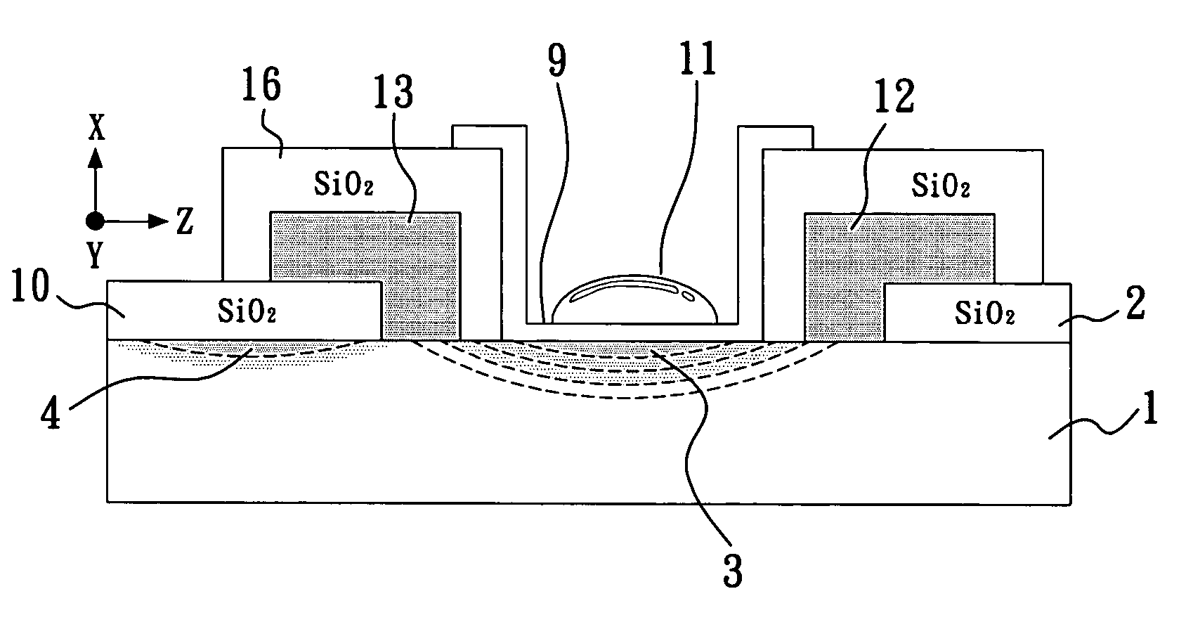
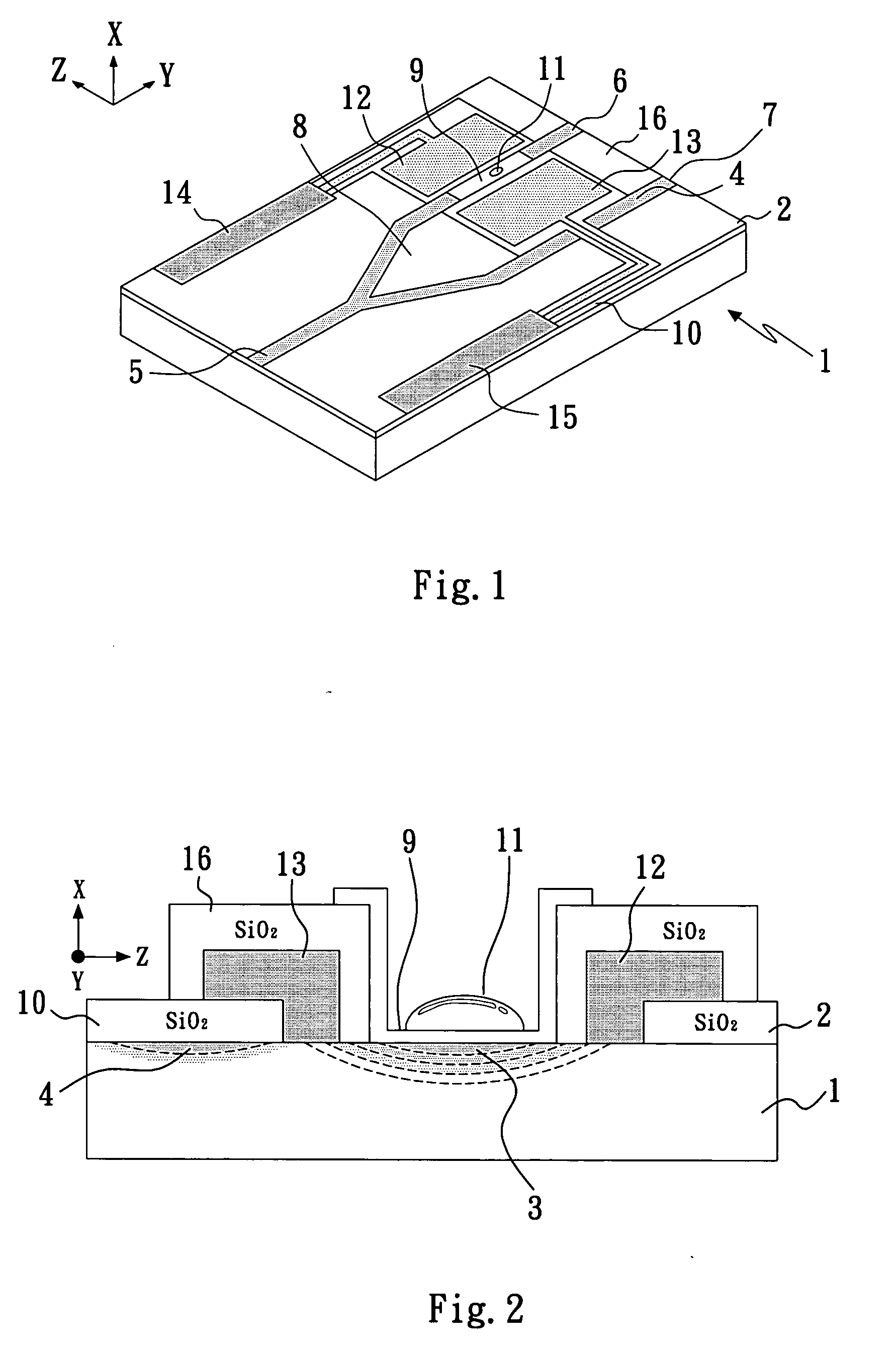
[0031] As shown in FIG. 1 and FIG. 2, a surface-plasmon-resonance sensing device based on the electro-optical effect of the present invention, provided on a substrate 1 with a surface 2, comprises a waveguide region consisting of a sensing waveguide 3 and a reference waveguide 4, and electrode section with two electrode ends 12 , 13 and two electrode input ends 14, 15. The substrate 1 is an X-cut lithium niobate crystal with the X-cut surface 2 which exhibits excellent electro-optical effect. Both the sensing waveguide 3 and the reference waveguide 4 are formed through localized in-diffusion of titanium ions across the substrate surface 2 into the lithium niobate crystal. Other ions, such as zinc and nickel, also can be used to produce the required waveguide in the lithium niobate crystal. Electromagnetic waves transmit essentially along a waveguide direction which is parallel to the Y-direction of the lithium niobate crystal. The sensing waveguide 3 and the reference waveguide 4 sh...


PUM


Abstract

The present invention provides a sensing method and device based on sensing surface plasmon resonance which can be controlled by the electro-optical modulation. In the case of an integrated-optic device according to the present invention, a voltage is applied on an electro-optical crystal substrate surface with waveguides to modulate the surface plasmon resonance condition on the sensing waveguide. Concentrations of chemicals or bio-chemicals contained in a sample placed on the sensing waveguide can be determined by measuring the dependence of the output light intensity on the applied voltage. Because spectrometer is not needed for measuring the surface plasmon resonance wavelength, drawbacks of conventional integrated-optic surface plasmon resonance sensors, like limited sensitivity, high cost and restrictions on circumstances for measuring, are avoided. The present invention can be applied for real-time dynamic analyses on sample's changes. Therefore, it can be extensively applied in the fields associated with tests of chemical gases and various solutions, pollution monitoring and bio-chips etc.

Description

BACKGROUND OF THE INVENTION [0001] 1. Field of the Invention [0002] The present invention relates to a sensing method and device based on the surface plasmon resonance techniques, particularly to a sensing method using the electro-optical modulation to detect surface plasmon resonance. It can be used to determine the concentrations of bio-chemical materials in a sample. Its application includes the following detections, such as determining the concentrations of a medicine, characterizing affinity of a medicine with human serum albumin, monitoring chemicals and environmental pollution, and elsewhere. [0003] 2. Description of the Prior Art [0004] Free charges in metal can be driven to move back and forth by an alternating electromagnetic field. The driven changing charge density leads to the so-called plasma oscillation. An electromagnetic wave incident on the metal can couple with the plasmon oscillation to produce the surface plasmon resonance, provided that proper conditions relate...

Claims


Application Information

Patent Timeline
IPC IPC(8): G01N21/55
CPCG01N21/1717G01N2201/067G01N2021/1721G01N21/553
Inventor WANG, TZYY-JIANNLIN, WEN-SHAO
Owner NAT TAIPEI UNIV OF TECH
Why Eureka
Try Eureka